


AC Servo Motors: Structure, Operation, Transfer Functions and Applications
Catalog
What is an AC Servo Motor?Key Features of AC Servo MotorsAC Servo Motor ConstructionWorking Principle of AC ServomotorsTransfer Function of AC Servo MotorTransfer Function of AC Servo MotorAC Servo Motor Speed Control MethodsCharacteristics of AC Servo MotorAdvantages of AC Servo MotorsDisadvantages of AC Servo MotorsApplications of AC Servo MotorsRelated ArticlesA servomotor functions as a rotary actuator, primarily designed to convert electrical input signals into mechanical rotational motion. These motors operate on a servomechanism principle, where position feedback is used to regulate the motor’s speed and precise final position. A servomotor will rotate to a specific angle in response to the input signal provided.
Despite their compact size, servomotors are highly energy efficient. They are broadly categorized into two types: AC servomotors and DC servomotors, with the key distinction being the power supply they use. The performance of a DC servomotor relies solely on input voltage, while an AC servomotor’s performance is determined by both voltage and frequency.
This article focuses on AC servomotors—covering how they work, along with their practical applications.
What is an AC Servo Motor?
An AC servo motor is a class of servomotor that produces mechanical output from an AC electrical input, delivering highly precise angular velocity and position control.
These motors typically offer output power ranging from a few watts up to several hundred watts, with an operating frequency span of 50 Hz to 400 Hz. A diagram of an AC servo motor is shown below.
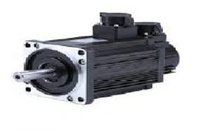
AC Servo Motor
Key Features of AC Servo Motors
- Lightweight construction
- Stable and reliable operation
- Low noise during operation
- Linear torque-speed characteristics
- Reduced maintenance requirements due to the absence of slip rings and brushes
AC Servo Motor Construction
An AC servo motor is typically designed as a two-phase induction motor. Like a standard induction motor, its basic structure consists of a stator and a rotor.
The stator of an AC servo motor usually features a laminated core, with two separate winding sets arranged 90° electrically apart from each other. This phase displacement creates a rotating magnetic field within the motor.
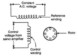
AC Servo Motor Construction
One winding is referred to as the main winding, also known as the fixed phase or reference winding. This winding is energized by a constant-voltage power supply.
The second winding, called the control winding or control phase, is powered by a variable control voltage typically supplied by a servo amplifier.
Rotors for AC servo motors generally come in two designs: squirrel-cage rotors and drag-cup rotors.
A standard squirrel-cage rotor uses aluminum conductors set in slots and short-circuited at both ends by end rings. The air gap is kept as small as possible to maximize magnetic flux linkage.
The drag-cup rotor is mainly used in applications requiring low rotational inertia, which helps reduce overall power consumption.
Working Principle of AC Servomotors
The operating principle of an AC servo motor is as follows:
A fixed AC voltage is first applied to the main winding on the stator, while the second stator winding — the control winding — is connected to a control transformer.
Driven by this reference voltage, the shaft of the synchronous unit rotates at a defined speed and achieves a precise angular position.
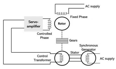
AC Servo Motor Circuit
Furthermore, the shaft position of the control transformer is compared with that of the synchro generator shaft. This comparison of angular positions generates an error signal. More specifically, the voltage levels corresponding to the two shaft positions are measured, producing the error signal relative to the actual voltage at the control transformer.
This error signal is then fed into a servo amplifier, which supplies a variable control voltage to the motor. Driven by this voltage, the rotor accelerates to a set speed and begins rotating, continuing until the error signal is reduced to zero — at which point the motor reaches and holds its desired position.
Transfer Function of AC Servo Motor
The transfer function of an AC servo motor is defined as the ratio of the Laplace transform of the output variable to the Laplace transform of the input variable. It serves as a mathematical model representing the differential equation that describes the input-output relationship of the system.
Once the transfer function of a system is known, the output response can be determined for various types of input signals, allowing us to characterize the system’s behavior. Conversely, if the transfer function is unknown, it can be identified experimentally by applying known input signals to the motor and analyzing the corresponding output response.
An AC servo motor is a two-phase induction motor, meaning it includes two windings: the control winding (main field winding) and the reference winding (excitation winding).
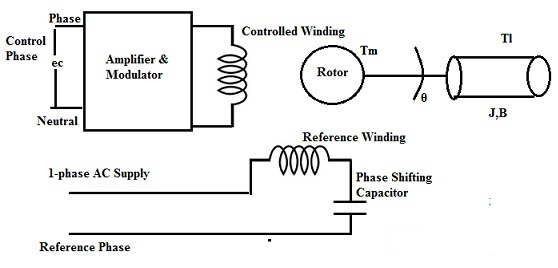
AC Servo Motor for Transfer Function
Transfer Function of AC Servo Motor
Our goal is to derive the transfer function of an AC servo motor, expressed as θ(s) / Eₙ(s),
where θ(s) is the system output (angular displacement) and Eₙ(s) is the system input (control voltage).
To obtain the transfer function, we analyze the motor-developed torque Tₘ and the load torque Tₗ,
then apply the torque equilibrium condition:
Tₘ = Tₗ
Define Variables
- Tₘ = torque developed by the motor
- Tₗ = load torque
- θ = angular displacement
- ω = dθ/dt = angular velocity
- J = moment of inertia of the load
- B = damping coefficient of the load
- K₁ = slope of control voltage–torque characteristics
- K₂ = slope of speed–torque characteristics
Torque Equations
Motor torque:
Tm=K1ec−K2dtdθ(1)
Load torque (due to inertia and damping):
Tl=Jdt2d2θ+Bdtdθ(2)
Equilibrium Condition
K1ec−K2dtdθ=Jdt2d2θ+Bdtdθ
Apply Laplace Transform (zero initial conditions)
K1Ec(s)−K2sθ(s)=Js2θ(s)+Bsθ(s)
Rearrange:
K1Ec(s)=θ(s)(Js2+Bs+K2s)
Ec(s)θ(s)=Js2+(B+K2)sK1
=s(B+K2+Js)K1
=s(1+B+K2Js)B+K2K1
Final Form
Ec(s)θ(s)=s(1+Tms)Km
Where:
- Kₘ = K₁ / (B + K₂) = motor gain constant
- Tₘ = J / (B + K₂) = motor time constant
AC Servo Motor Speed Control Methods
Servo motors typically support three control modes:
position control, torque control, and speed control.
Position Control
In position control, motor rotation speed is determined by an external reference frequency,
and rotation angle is controlled by the number of input pulses.
Both position and velocity can be set directly via communication commands.
This mode provides extremely precise position and speed regulation,
making it ideal for high-precision positioning applications.
Torque Control
Torque control sets the motor’s output torque using an analog input.
Torque can be adjusted in real time by modifying the analog signal,
or updated by writing to a designated register via fieldbus communication.
Speed Control
In speed control mode, motor speed is regulated via analog inputs or pulse signals.
This mode is preferred when high speed accuracy is required and precise torque control is less critical.
Characteristics of AC Servo Motor
The torque-speed characteristics of an AC servo motor are illustrated below.
In these characteristics, torque varies with speed in a non-linear manner, as the relationship largely depends on the motor’s reactance-to-resistance ratio (X/R).
A low X/R ratio means the motor has high resistance and low reactance. Under these conditions, the motor’s torque-speed curve is significantly more linear.
Conversely, a high X/R ratio results in a much less linear torque-speed profile.
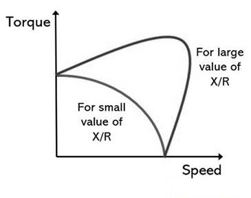
Torque Speed Characteristics
Advantages of AC Servo Motors
- Excellent speed control characteristics
- Low heat generation
- High efficiency, high torque-to-weight ratio, high reliability, and low RF noise
- Low maintenance requirements
- Longer service life due to the absence of a commutator
- Ability to withstand high current surges in industrial equipment
- More stable torque at high speeds
- High operational reliability
- Excellent high-speed performance
- Well suited for applications with fluctuating or unstable loads
Disadvantages of AC Servo Motors
- More complex to control
- Prone to damage under continuous overload conditions
- Often require gearboxes to deliver power effectively at high speeds
Applications of AC Servo Motors
AC servo motors are widely used where precise position control is critical, commonly found in:
- Semiconductor manufacturing equipment
- Robotics and industrial robots
- Aerospace and aviation systems
- Machine tools
- Servomechanism-based instruments such as computer peripherals and precision positioning devices
- Tracking systems
Thanks to their high efficiency and versatility, they are employed across numerous industries.
They also appear in many general machinery and everyday devices including water heaters, ovens, pumps, off-road vehicles, and garden equipment.
In fact, many common household appliances and tools are driven by AC servo motors.
This covers the fundamentals of AC servo motors, including their operating principle and applications.
Now here’s a question for you: What is an induction motor?
Related Articles
Diode Dynamics: Real-World Behavior in Fast Power and RF Circuits

Amanda Miller
Amanda Miller is a senior electronics engineer with 6 years of experience. She focuses on studying resistors, transistors, and package design in detail. Her deep knowledge helps her bring innovation and high standards to the electronics industry.
Subscribe to JMBom Electronics !


