


ADXL335 Accelerometer Sensor: Pinout, Specs, Features, and How It Works
Catalog
What Is the ADXL335 Accelerometer?How Does the ADXL335 Work?ADXL335 Accelerometer Pinout OverviewADXL335 Accelerometer Module: Hardware OverviewHow to Connect the ADXL335 Accelerometer to an Arduino UnoDifference between the ADXL335 & ADXL345 ModulesCommon Applications of the ADXL335 AccelerometerFinal Thoughts on the ADXL335 Accelerometer ModuleADXL335 Accelerometer Sensor – Frequently Asked Questions (FAQs)Related ArticlesHave you ever thought about how your smartphone knows when to rotate the screen from portrait to landscape? Or how fitness bands track if you're walking, running, or just standing still? The answer lies in a tiny yet powerful device called an accelerometer. These sensors are built into modern devices to detect motion, tilt, and orientation. One of the most affordable and widely used options is the ADXL335 accelerometer sensor module. This compact, low-power sensor is commonly found in electronics projects for measuring acceleration along three axes: X, Y, and Z. In this article, we’ll take a closer look at what the ADXL335 is, how it works, and where it's used.
What Is the ADXL335 Accelerometer?
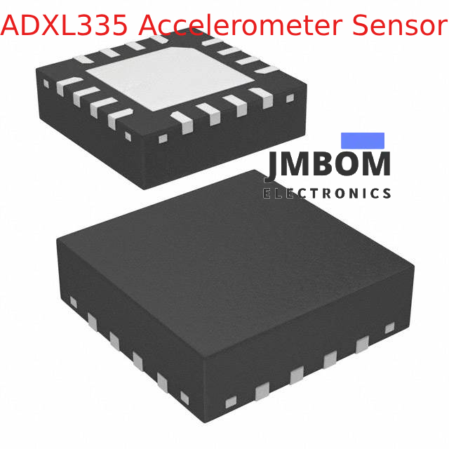
The ADXL335 is a compact, low-power 3-axis accelerometer from Analog Devices. It’s designed to sense acceleration along the X, Y, and Z axes and outputs an analog voltage for each axis that corresponds to the acceleration being experienced. This makes it ideal for detecting movement, tilt, or orientation in a wide variety of applications—ranging from smartphones and gaming controllers to robotics and wearable devices. Its small footprint and minimal power consumption make it perfect for projects that require reliable motion detection, vibration monitoring, or tilt sensing.
How Does the ADXL335 Work?
The ADXL335 operates on the principle of capacitive sensing to measure acceleration across all three axes. In simple terms, acceleration causes internal components of the sensor to shift, which leads to a change in capacitance. These changes are then converted into analog voltage signals. The module is based on MEMS (Micro-Electro-Mechanical Systems) technology and contains a small internal mass suspended by tiny springs. When acceleration occurs, the mass shifts slightly, and this motion is detected and translated into voltage changes corresponding to the amount and direction of acceleration.
Understanding ADXL335 Output Signals and Pin Description
When acceleration is applied, the internal mass of the sensor shifts slightly. This movement changes the capacitance between the moving mass and the fixed elements inside the module. These variations in capacitance are then translated into analog voltage signals.
The ADXL335 outputs analog signals for each of the three axes (X, Y, and Z). These signals are directly proportional to the acceleration experienced along each axis. Under normal conditions—when no acceleration is applied—the output voltage is around 1.65V (which is half of the typical 3.3V supply). As acceleration increases in a given direction, the output voltage for that axis will either increase or decrease relative to this midpoint. For example, a positive acceleration along the X-axis will push the X-axis output voltage above 1.65V.
ADXL335 Accelerometer Pinout Overview
The pin configuration for the ADXL335 sensor module is as follows:
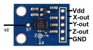
ADXL335 sensor module
- Pin 1 (VCC): This pin supplies power to the sensor. It should be connected to the 5V pin of an Arduino or compatible microcontroller.
- Pin 2 (X-Out): Outputs an analog voltage corresponding to acceleration along the X-axis.
- Pin 3 (Y-Out): Provides an analog voltage that reflects acceleration along the Y-axis.
- Pin 4 (Z-Out): Delivers an analog voltage in response to acceleration on the Z-axis.
- Pin 5 (GND): Ground pin for the module; it must be connected to the system GND.
- Pin 6 (ST - Self-Test): This pin is used for self-testing the sensor to ensure it’s functioning properly during operation.
ADXL335 Accelerometer: Key Features and Technical Specs
Here are the main features and specifications of the ADXL335 3-axis accelerometer module:
- The ADXL335 is a 6-pin accelerometer module.
- It comes in a compact, low-profile LFCSP_LQ package.
- It is a cost-effective, widely available, and space-saving sensor.
- The operating voltage range is 3V to 6V DC.
- It draws a low operating current of about 350μA.
- The measurement range is ±3g (for each axis).
- Supports three-axis sensing (X, Y, and Z).
- Highly responsive to slight movements.
- No external components are needed for basic operation.
- Easy to interface with standard analog/digital ICs and microcontrollers.
- Provides three separate analog voltage outputs, each corresponding to acceleration on one of the three axes.
- Offers full ±3g range for acceleration measurement with a supply voltage between 1.8V and 3.6V.
- The analog outputs are ideal for direct connection to ADCs (Analog-to-Digital Converters) or microcontroller input pins.
- Typical sensitivity is 300mV/g at 3.0V and 330mV/g at 3.3V supply voltage.
- Both the sensitivity and zero-g bias voltage are ratiometric, meaning they scale in proportion to the supply voltage.
- Operates reliably in temperatures from -40°C to +85°C.
- Can be stored at temperatures between -65°C and +150°C.
- The sensor’s bandwidth (BW) can be configured individually for each axis: X and Y axes: adjustable from 0.5 Hz to 1600 Hz Z axis: adjustable from 0.5 Hz to 550 Hz
ADXL335 Accelerometer Module: Hardware Overview
The ADXL335 accelerometer module consists of several key components, including the ADXL335 sensor chip, a 3.3V voltage regulator, and a self-test function. Here's a breakdown of each:
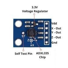
ADXL335 Accelerometer Sensor Hardware
ADXL335 Sensor Chip
At the core of the module is the ADXL335 IC, a compact, low-power 3-axis accelerometer that measures acceleration along the X, Y, and Z axes. It’s widely used in mobile devices, gaming consoles, and hobby electronics where motion or tilt detection is needed. The chip outputs analog voltage signals proportional to the acceleration on each axis and supports a full-scale range of ±3g.
3.3V Voltage Regulator
To ensure compatibility with a variety of microcontrollers, the module features an onboard 3.3V voltage regulator. This allows the module to operate safely with both 3.3V and 5V systems. While the sensor itself operates in a voltage range of 1.8V to 3.6V, the regulator simplifies integration by providing a stable 3.3V typical operating voltage.
Self-Test Capability
The module also includes a self-test function that lets you verify if the sensor is working correctly. To run the self-test, connect the ST (Self-Test) pin to a 3.3V supply. This applies a small electrostatic force inside the sensor, causing a shift in the internal MEMS structure.
When the self-test is active, you should observe a noticeable change in the output readings. After testing, the ST pin should either be left floating or connected to GND.
Acceleration Range
The sensor supports a measurement range of ±3g, meaning it can detect accelerations up to three times the force of gravity in any direction. While the sensor can survive shocks of up to 10,000g, measurements beyond ±3g will max out at that range and won’t reflect higher values accurately. Exceeding its physical limits could lead to permanent damage.
Ratiometric Output
The ADXL335 produces a ratiometric output, which means its output voltage varies linearly with both the applied acceleration and the supply voltage.
- With no acceleration, each axis typically outputs around 1.65V (half of 3.3V).
- At -3g, the output drops close to 0V.
- At +3g, the output approaches 3.3V. This smooth linear response makes it easy to interpret changes in motion using analog-to-digital converters (ADCs).
Equivalent and Alternative Sensors
Some equivalent accelerometer ICs to the ADXL335 include:
ADXL345, ADXL356, MMA8452Q, LIS3DH, BMA220, and MPU-6050.
Alternative sensor modules you might consider depending on your project needs include:
LDR module, IR sensor, TP4056 Li-ion charger, DS3231 RTC, DRV8825 stepper driver, TMC2209, joystick module, A4988 driver, EM-18 RFID reader, NEO-6M GPS, GLCD 128×64, and HMC5883L magnetometer.
How to Connect the ADXL335 Accelerometer to an Arduino Uno
You can easily interface the ADXL335 3-axis accelerometer with an Arduino Uno to measure movement along the X, Y, and Z axes. The acceleration values can then be shown on a 16x2 LCD display. This setup is perfect for motion-detection projects and tilt-sensing applications.
Components Needed
To build this setup, you’ll need the following:
- ADXL335 Accelerometer Module
- Arduino Uno Board
- 16×2 LCD Display (I2C or parallel)
- Breadboard
- Jumper Wires
- 5V DC Power Supply
Wiring the ADXL335 to Arduino Uno
Here's how to wire the components:
Accelerometer to Arduino
- Connect X-Out (ADXL335) → A0 (Arduino analog input)
- Connect Y-Out → A1
- Connect Z-Out → A2
- Connect VCC → 5V (Arduino power output)
- Connect GND → GND (Arduino ground)
LCD to Arduino (I2C version)
- VCC → 5V
- GND → GND
- SDA → A4
- SCL → A5
This setup lets the Arduino read the accelerometer's outputs and display them in real-time on the LCD screen.
Arduino Code Example
Below is a sample sketch written in C++ for Arduino. This code reads acceleration values from the ADXL335 and shows them on a 16x2 LCD.
cppCopyEdit#include <LiquidCrystal.h>
LiquidCrystal lcd(12, 11, 5, 4, 3, 2);

int xpin = 0;
int ypin = 1;
int zpin = 2;

int Xread, Xrest;
int Yread, Yrest;
int Zread, Zrest;

double Gx, Gy, Gz;
int t1;

void setup() {
  Serial.begin(9600);
  lcd.begin(16, 2);
  digitalWrite(13, HIGH);
  delay(1000);

  // Baseline (zero-g) values
  Xrest = analogRead(xpin);
  Yrest = analogRead(ypin);
  Zrest = analogRead(zpin);

  digitalWrite(13, LOW);
}

void loop() {
  Serial.print("Time: ");
  t1 = millis();
  Serial.println(t1 * 0.001);

  // Get the adjusted acceleration readings
  Xread = analogRead(xpin) - Xrest;
  Yread = analogRead(ypin) - Yrest;
  Zread = analogRead(zpin) - Zrest;

  Gx = Xread / 67.584;
  Gy = Yread / 67.584;
  Gz = Zread / 67.584;

  // Print to Serial Monitor
  Serial.print("Acceleration X: "); Serial.print(Gx);
  Serial.print(" Y: "); Serial.print(Gy);
  Serial.print(" Z: "); Serial.println(Gz);

  // Print to LCD
  lcd.setCursor(0, 0);
  lcd.print("gx:");
  lcd.print(Gx);
  lcd.setCursor(8, 0);
  lcd.print("gy:");
  lcd.print(Gy);
  lcd.setCursor(0, 1);
  lcd.print("gz:");
  lcd.print(Gz);

  delay(1000);
  lcd.clear();
}
How to Use It
- Copy and paste the code into the Arduino IDE.
- Upload the sketch to your Arduino Uno.
- Move the ADXL335 sensor gently in various directions.
- Watch as the LCD updates with the live acceleration values along the X, Y, and Z axes.
This simple demonstration shows how the ADXL335 can be used with an Arduino to detect movement and display acceleration data in real-time.
Difference between the ADXL335 & ADXL345 Modules
The difference between the ADXL335 & ADXL345 accelerometer modules includes the following.
| ADXL335 | ADXL345 |
| The ADXL335 accelerometer module uses an analog communication protocol for analog voltage outputs. | The ADXL345 accelerometer module communicates with either SPI or I2C protocols. |
| It is an analog accelerometer, so it outputs analog voltage values for every X, Y, & Z axis. | It is a digital accelerometer that outputs 3-axis acceleration measurements in digital format. |
| This module doesn’t have built-in features like sleep modes, selectable g-ranges, and free-fall detection. | This module includes different features like activity/freefall detection, better sensitivity, on-board FIFO, etc. |
| It has fewer advanced features. | It has more advanced features. |
| This module can be used where analog output is chosen, like simple tilt-sensing, motion detection-based applications | This module can be used where digital communication is required, like robotics, mobile devices, etc. |
| Its range is ±3g. | Its range is up to ±16g. |
Benefits of Using the ADXL335 Accelerometer Module
The ADXL335 offers several key advantages that make it a practical choice for motion-sensing applications:
- Low Power Consumption: Requires as little as 320µA, making it ideal for battery-powered devices.
- Compact Design: Its small footprint allows for easy integration into compact or embedded systems.
- Easy-to-Use Analog Interface: No complex communication protocol is required — simply connect to an analog input.
- 3-Axis Sensing: Measures acceleration on the X, Y, and Z axes for full 3D motion detection and orientation analysis.
- Versatile Applications: Can be used in a wide range of devices, from wearables to robotics.
- Budget-Friendly: An economical option for both hobbyists and product developers.
- Straightforward Output: The analog signals are directly proportional to acceleration and can be easily processed by microcontrollers or analog circuits.
- Shock Tolerance: Built to withstand shocks up to 10,000g, ensuring high durability in rugged environments.
Limitations of the ADXL335 Module
Despite its benefits, there are a few trade-offs to consider:
- Limited Measurement Range: Can only detect acceleration up to ±3g, which may not be sufficient for high-impact or high-speed applications.
- Noise Sensitivity: The output can be affected by electrical noise, which may reduce measurement accuracy.
- External Processing Required: Analog outputs need to be read and interpreted using an external ADC or microcontroller.
- ADC Dependency: Requires an analog-to-digital converter, adding a small layer of complexity and cost.
- Zero-G Drift: The baseline output can drift over time or due to temperature changes, requiring periodic recalibration.
- Yaw Measurement Limitation: Cannot accurately detect rotation around the Z-axis on its own, as angular velocity doesn’t produce linear acceleration on that axis.
Common Applications of the ADXL335 Accelerometer
The ADXL335 is widely used in various fields due to its reliability and simplicity:
- Mobile Devices: Enables features like power management, screen rotation, and fall detection.
- Drones & RC Vehicles: Helps maintain balance and detect motion changes for stability control.
- GPS Systems: Enhances data collection by tracking motion and acceleration.
- Impact Detection Systems: Records and monitors impacts during crashes or mechanical stress events.
- Gaming & VR Devices: Translates tilt and motion into control input for immersive experiences.
- Motion-Triggered Features: Used to wake up displays or activate functions when movement is detected.
- Wearables & Smart Devices: Found in fitness trackers, smartwatches, and phones for motion sensing and gesture control.
- Industrial & Scientific Tools: Used in vibration analysis, machinery monitoring, earthquake sensing, and inertial navigation systems (INS).
Final Thoughts on the ADXL335 Accelerometer Module
In summary, the ADXL335 accelerometer sensor is a compact and efficient solution for detecting acceleration in three dimensions. Its simple design, low power usage, and ability to sense both static and dynamic acceleration make it a reliable choice for a wide variety of motion-sensing applications — from wearable tech to robotics and beyond.
Its versatility and ease of integration have made it a popular component in countless DIY and commercial projects.
Now a quick question for you:
Have you heard of the ADXL345 module — and how does it compare to the ADXL335?
ADXL335 Accelerometer Sensor – Frequently Asked Questions (FAQs)
What is the ADXL335 accelerometer?
The ADXL335 is a compact, low-power, 3-axis accelerometer that outputs analog voltage signals corresponding to acceleration along the X, Y, and Z axes. It supports a full-scale measurement range of ±3g and comes with built-in signal conditioning for easy integration.
How can I fix an issue with the accelerometer sensor on my device?
To recalibrate the accelerometer sensor, follow these steps:
- Power off your device and boot into recovery mode (press and hold the Power + Volume Up buttons).
- Navigate to the sensor test menu.
- Select the accelerometer test option.
- Place your device on a flat, level surface and tap the "Calibrate" button.
- Once calibration is complete, run directional tests (e.g., X-, X+, Y-, Y+, 45° tilt) to ensure proper sensor functionality.
- Save the calibration settings before exiting.
What is the ADXL345 accelerometer used for?
The ADXL345 is designed for both static tilt sensing and dynamic motion detection. It measures gravitational acceleration and is commonly used in applications such as motion tracking, vibration analysis, and astronomy equipment—like observing how a dome moves to align with a celestial object. Sample vibration values measured include 0.2356 m/s², 0.2707 m/s², and 0.3056 m/s².
What is the main function of an accelerometer?
An accelerometer detects acceleration or vibrations affecting a structure or device. When the device moves or experiences force, a mass inside compresses a piezoelectric element or alters capacitance, generating a corresponding electrical signal that represents the amount of acceleration.
What types of motion can an accelerometer detect?
Accelerometers can measure:
- Acceleration and deceleration (e.g., braking or speeding up)
- Sudden impacts or shocks
- Tilting and orientation changes
- Vibrations or jolts
- Lateral forces like those encountered during sharp turns
How do I test if my accelerometer is working properly?
To perform a basic static calibration:
- Place the accelerometer on a level, stable surface.
- Let it experience a known static force, such as gravity (1g).
- Record the sensor's output and compare it with the expected value.
- If there’s a discrepancy, apply software-based offset correction or recalibrate using your device’s diagnostic tools.
Related Articles
TLV3201AQDCKRQ1 Comparator: Pinout, Operation, and Typical Uses
OPT3007 Ultra-Thin Ambient Light Sensor Overview and Applications
TPS7A26 LDO Regulator: Functionality and Key Applications
Guide to Low Dropout (LDO) Regulators and How They Work
ESP32-S3 Development Board: Pinout Diagram, Key Features, Technical Specs
DS18B20 Waterproof Temperature Sensor: Overview, Operation, and Common Uses
BAT54A Schottky Diode: Pinout and Common Uses
Infineon ILD8150E LED Driver IC Overview
LF353N Op-Amp Explained: Pinout, Features, and How It Works

Christopher Anderson
Christopher Anderson has a Ph.D. in electrical engineering, focusing on power electronics. He’s been a Senior member of the IEEE Power Electronics Society since 2021. Right now, he works with the KPR Institute of Engineering and Technology in the U.S. He also writes detailed, top-notch articles about power electronics for business-to-business electronics platforms.
Subscribe to JMBom Electronics !


