


Remote Control Light Switches: Principle & Applications
Catalog
What Is a Remote Control Light Switch?TransmissionReceptionAdvantages & DisadvantagesApplicationsRelated ArticlesIn industrial settings, remote control switches enable load control without the need for physical cabling. Cabling typically requires greater maintenance, as it tends to degrade more rapidly in harsh industrial environments. Remote control switches allow operators to manage equipment or machinery from any location, helping to save valuable time and boost operational efficiency. They also enhance safety, protecting operators from potential accidental injuries. This article provides a comprehensive overview of remote control light switches, including their operating principles and practical applications.
What Is a Remote Control Light Switch?
A remote control light switch is a device designed to control a connected load—such as an AC lighting fixture—by switching it on and off remotely. Remote controls are widely used to operate a variety of household electronics, including televisions, audio systems, air conditioners, DVD players, and more.
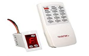
Remote Control Light Switch
This is a low-cost switch with a straightforward design.
It is used to remotely control household electrical appliances.
The switch consists of two main components: a transmitter and a receiver.
The transmitter functions as a standard remote control, while the receiver remains stationary and connects to the electrical load.
Remote Controlled Light Switch Block Diagram
The block diagram of the remote-controlled light switch is illustrated below. It comprises a transmitter section and a receiver section, which are explained in detail as follows.
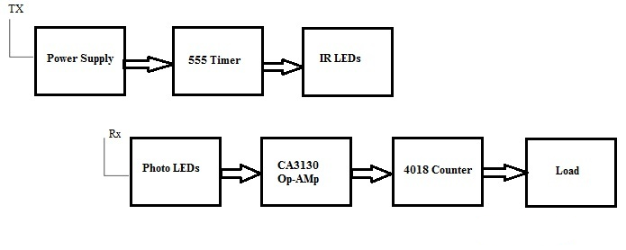
Block Diagram
The transmitter section consists of a power supply, an NE555 timer, and IR LEDs.
In this configuration, the NE555 timer is operated in astable mode. IR LEDs are employed, with their infrared radiation focused through a concave lens, and the circuit is powered by a 9V battery.
The switch integrated into the transmitter circuit serves a critical function.
When the switch is closed, battery power activates the NE555 timer, which operates as an astable multivibrator. The IR LEDs are connected to the output of the NE555 and emit an infrared signal through the concave lens.
When the infrared beam transmitted by the transmitter is received by the receiver section, the photodiodes detect the IR signal and charge a capacitor, increasing the input voltage at one pin of the op‑amp, resulting in a high output signal.
This high output from the op‑amp is then fed to the 4018 counter, which in turn drives the load via a relay to achieve the desired control operation.
Remote Control Light Switch Circuit Diagram
The circuit diagram for the remote control light switch is illustrated below.
The components required for the circuit are as follows: a CD4017 decade counter IC, a 12V relay, an AC light bulb, a bulb holder, a BC558 PNP transistor, a small remote control, a 2N2222 NPN transistor, two 1 kΩ resistors, one 10 kΩ resistor, a 1N4007 PN junction diode, and a TSOP1738 IR receiver.
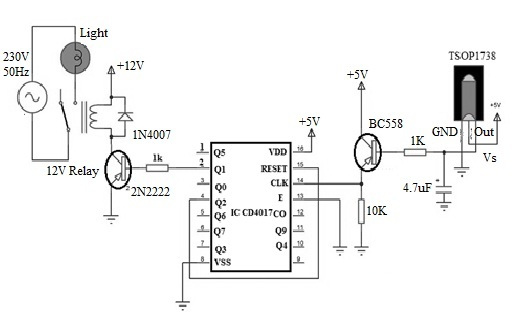
Remote Controlled Light Switch Circuit Diagram
The key components utilized in this circuit are the TSOP1738 infrared receiver and the CD4017 integrated circuit.
The output of the infrared receiver is a decoded signal originating from the remote control.
This decoded output signal is supplied to the base of a PNP transistor through a 1 kΩ resistor.
Additionally, a capacitor is connected between the output of the TSOP1738 infrared receiver and ground to stabilize the output signal level.
The emitter terminal of the transistor is connected to the clock (CLK) input of the CD4017 IC.
The enable pin, also referred to as the clock inhibit pin, is tied to ground.
Pin Q2 (Output 2) of the CD4017 is connected to Pin 15, the reset pin.
Finally, Pin 3 (output) is connected to the input of the relay module.
How Does a Remote Control Light Switch Work?
This project demonstrates a straightforward application: a remote-controlled load switch used to switch an AC light on and off.
The device operates in two stages: transmission and reception, which are explained in detail below.
Transmission
In the transmission stage, whenever a button on the remote control is pressed, it transmits a modulated infrared (IR) signal.
This signal is detected by the TSOP1738 receiver, which then demodulates the signal and produces a corresponding output.
The output of the TSOP1738 is low when it successfully detects and demodulates the IR signal.
Since this output is connected to the input of the PNP transistor, the transistor switches on whenever a button on the remote is pressed.
As a result, the clock (CLK) pin of the CD4017 decade counter IC receives a positive edge transition, causing the Q1 output to go high.
The Q1 pin of the CD4017 is connected to the input of the relay module, which then activates and turns on the light.
Reception
When a button on the remote is pressed again, the TSOP output goes low once more, turning the PNP transistor on.
The CLK pin of the CD4017 receives another low-to-high transition, causing the Q2 output to go high.
As the Q2 output is connected to the reset (RST) pin of the CD4017 IC, the decade counter resets, and the Q1 output returns low.
This deactivates the relay, turning the light off.
If any button on the remote is pressed again, the IC will trigger once more, and the Q1 output will go high to turn the light back on.
How to Install a Remote Control Light Switch
When shopping for a remote control light switch, you’ll find various options available. However, before making a final choice, it’s essential to select the control system that best suits your home’s needs. A basic remote control light switch allows you to wirelessly adjust your home’s lighting functions and brightness—either from inside or outside the house—using your smartphone.
The following steps outline how to install a remote control light switch:
Step 1: Turn Off the Power
Prior to installing the remote lighting switch, shut off the circuit breaker. To verify it’s disconnected, flip the light switch and confirm the light turns off. Never attempt installation while power is active to avoid electric shock.
Turn off the Power
Connect the Switch
Disconnect the wiring and remove the existing conventional switch.
Connect the corresponding wires to the remote control switch as instructed.
Mount the switch securely into the wall electrical box in the same manner as a standard switch, then secure the cover plate with screws.
Connect the Switch
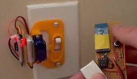
Mount the Receiver
Remove the bulb from the lighting fixture and unscrew the mounting clip from the fixture housing. Carefully pull the fixture out to access the internal wiring.
Inspect the remote control system and identify the wires that need to be connected to the receiver.

Lightning Fixture
Program the Remote
First, switch the circuit breakers back on, then power on the remote control.
Follow the manufacturer’s instructions to program the remote.
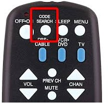
Program the Remote
Test the Remote
Test the remote control function by switching the light on and off several times to ensure proper operation.
If the system includes a dimmer, verify its dimming range and functionality.
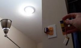
Check the Remote
What Can a Remote Control Switch Be Used For?
Remote control switches are compatible with most lights and electrical appliances.
They can be used with your TV and cable box, DVD or Blu-ray player, stereo system, computer monitor, speakers, and more—essentially any device powered by electricity.
How to Activate a Remote Control Switch
Follow these steps to turn on your remote control switch:
- First, ensure your smartphone is connected to a Wi‑Fi network or has cellular data service.If not, verify your internet service provider (ISP) connection and that coverage is available in your area.
- Next, launch the pre-installed remote control app on your phone and tap “Add Switch”.A list of available switches will appear—select your device from the list and tap “Done”.
- You will be prompted to grant location services permission for the app.
Advantages & Disadvantages
Advantages of Remote Control Light Switches
- Operation is hassle-free and highly convenient.
- Helps conserve energy.
- Particularly beneficial for the elderly and individuals with disabilities.
- Low cost and easy to construct.
- The circuit can be integrated with a microcontroller to control multiple loads, with each remote button assigned to a different device.
- The system can also be implemented using an Arduino platform.
Disadvantages of Remote Control Light Switches
- Basic designs typically control only a single load.
- Limited wireless communication range.
- Wireless systems may suffer from reduced reliability.
- Require regular maintenance.
Applications
- Used for switching AC lights on and off.
- Adds smart home automation capabilities to residential settings.
This article provides a complete overview of the remote control light switch, a widely used solution in home automation.This type of switch enables convenient control of indoor and outdoor lighting intensity via wireless remote technology.Here is a question for you: What is an IR sensor?
Related Articles
AC Servo Motors: Structure, Operation, Transfer Functions and Applications

Christopher Anderson
Christopher Anderson has a Ph.D. in electrical engineering, focusing on power electronics. He’s been a Senior member of the IEEE Power Electronics Society since 2021. Right now, he works with the KPR Institute of Engineering and Technology in the U.S. He also writes detailed, top-notch articles about power electronics for business-to-business electronics platforms.
Subscribe to JMBom Electronics !


