


NTC Thermistor: Working Principle & Applications
Catalog
What is an NTC thermistor?NTC Thermistor Working PrincipleNTC Thermistor SpecificationsTypes of NTC ThermistorNTC Thermistor Circuit DiagramDifference Between NTC Thermistor and PTC ThermistorAdvantages, Disadvantages, and Applications of NTC ThermistorsRelated ArticlesThe first NTC thermistor was discovered by Michael Faraday in 1833, when he published a report on the semiconducting properties of silver sulfide. He observed that the resistance of silver sulfide decreased significantly as temperature rose. Early thermistors were difficult to manufacture, and their technological applications were limited. As a result, commercial production of thermistors did not begin until the 1930s.
In 1930, Samuel Ruben introduced a commercially viable thermistor known as “Duracell”. Following this, research into NTC thermistors advanced significantly thanks to progress in continuous transistor technology. Ultimately, modern NTC thermistors were developed in 1960. This article explores NTC thermistors, their working principle, and applications.
What is an NTC thermistor?
NTC stands for “Negative Temperature Coefficient”. An NTC thermistor is a type of resistor whose resistance decreases as temperature rises. These devices are primarily used as current-limiting components and resistive temperature sensors. The symbol for an NTC thermistor, in accordance with IEC standards, is shown below.
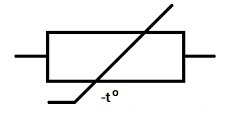
NTC Thermistor Symbol
When compared to silistors or silicon temperature sensors, the temperature sensitivity coefficient of these thermistors is five times greater, and ten times higher than that of RTDs (resistive temperature detectors). The materials that are employed in the manufacture of these thermistors include nickel, iron, copper, manganese, and cobalt. The operating temperature range for these resistive devices extends from −55°C to +200 °C.
NTC Thermistor Working Principle
The working principle of an NTC thermistor is mainly dependent on the ambient temperature. When the temperature of the thermistor increases, its resistance will decrease. For every 1-degree centigrade rise in temperature, the resistance will decrease by 5%.
There are two factors that affect a material’s resistance to electrical flow: the number of free electrons in the material and the ease with which they can move through it. The latter is influenced by the crystal structure of the material, which will have more or fewer “free-electron paths” for the current to flow through.
NTC thermistors are made from ceramics that contain metal oxides, including Mn-Ni-Co oxide, Ni-Cr oxide, and Cu-Ni oxide, along with additives. When these metals are combined with oxygen, they form bonds that limit the number of free-electron paths in the crystal structure, thereby increasing resistance.
At higher temperatures, however, collisions between atoms cause the crystal structure to break down slightly, releasing some electrons and creating free-electron paths where they did not exist before. The more free-electron paths there are, the less resistance there is to electrical flow. That is how NTC thermistors exhibit a drop in resistance as temperature increases.
NTC Thermistor Specifications
- The specifications of an NTC thermistor include the following:
- The resistance is 10K ± 1% at 25 degrees Centigrade.
- The B-value is 3950 ± 1%.
- Its response time is very fast, ranging from 0.12 to 10 seconds.
- The dissipation factor δth is approximately 7.5mW/K.
- The thermal cooling time constant is ≤ 20 seconds.
- The temperature range is from -55 °C to +200 °C.
- There are two available terminals.
- The linearity is exponential.
- Its accuracy ranges from 0.05°C to 1.00°C.
- The maximum tolerance is up to ±1.5% at –40°C and 150°C.
- Its cost ranges from low to moderate.
Types of NTC Thermistor
NTC thermistors are categorized into three main types according to their construction, as outlined in the following section.
Bead Thermistors
Bead thermistors are manufactured by directly molding platinum alloy lead wires into the ceramic sensing element. These devices are sealed inside glass encapsulation to prevent physical damage during assembly and to improve the stability of their temperature measurements.
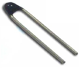
Bead type Thermistor
These types of thermistors are generally widely used because they offer superior stability, fast response times, and the ability to operate at higher maximum temperatures compared to other types such as chip and disk thermistors. Bead thermistors are compact in size, with diameters ranging from 0.075 mm to 5 mm. The most common varieties of bead-type thermistors include glass-coated beads and miniature glass probes.
Disk & Chip Thermistors
These types of NTC thermistors are manufactured with metallized surface contacts. They are larger in physical size and exhibit slower response times in comparison to bead-type thermistors. Owing to their greater size, these resistors feature a high dissipation constant. Since the power dissipation of these thermistors is proportional to the square of the applied current, they are capable of handling higher maximum currents than bead-type thermistors.
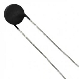
Disk & Chip Style Thermistor
Disk-type NTC thermistors are designed by pressing a mixture of oxide powders into a round die at high temperatures. Chip-type thermistors are typically designed using a tape-casting method, where a slurry of the material is spread as a thick film, dried, and cut into the desired shape. The size of these thermistors ranges from 0.25mm to 25 mm in diameter.
Glass Encapsulated NTC Thermistors
Glass encapsulated NTC thermistors are enclosed within a sealed glass bubble. These are small-sized thermistors that prevent resistance reading errors caused by moisture penetration. These thermistors operate efficiently in harsh environmental conditions and extreme temperatures. The temperatures at which these thermistors are used are above 150 °C. Encapsulating a thermistor within glass improves its stability and also shields it from the surrounding environment. The typical sizes of these thermistors range from 0.4 to 10 mm in diameter.
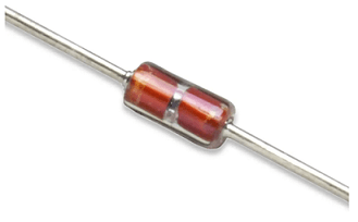
Glass Encapsulated Thermistor
NTC Thermistor Circuit Diagram
The circuit diagram for the temperature sensor is shown below. This circuit is primarily designed to control an automatic fan using an NTC thermistor. The function of this circuit is that when the temperature increases, the fan will automatically turn ON.
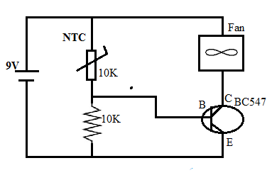
Fan Controller using NTC Thermistor
The components required to build this automatic fan controller circuit include a 10K NTC thermistor, a 10K resistor, a 9V battery, a fan, and a BC547 transistor.
The connections for this circuit can be made in accordance with the circuit diagram provided above. In this circuit, a 10kΩ NTC thermistor is connected in series with a 10kΩ resistor to form a voltage divider circuit. The resistance of this thermistor will increase when the temperature decreases, and its resistance will decrease when the temperature increases.
The resistance of the thermistor at room temperature is 10kohms. In this circuit, the fan is simply connected through the BC547 transistor. When the thermistor detects an increase in temperature, its resistance will decrease, which will cause the fan to turn ON. When the temperature decreases, the fan will turn OFF.
NTC Thermistor Resistance Table
The resistance of an NTC thermistor changes primarily based on temperature. The temperature specified by the thermistor manufacturer is generally 25°C. The following table shows the resistance values corresponding to different temperature values.
| Temperature | Resistance |
|---|---|
| 0°C | 30kΩ |
| 25°C | 10kΩ |
| 35°C | 1kΩ |
| 50°C | 4kΩ |
Difference Between NTC Thermistor and PTC Thermistor
The differences between an NTC thermistor and a PTC thermistor are as follows:
| NTC Thermistor | PTC Thermistor |
|---|---|
| In an NTC thermistor, the term “NTC” stands for Negative Temperature Coefficient. | In a PTC thermistor, the term “PTC” stands for Positive Temperature Coefficient. |
| In this type of thermistor, the resistance decreases when the temperature increases. | In this type of thermistor, the resistance increases when the temperature increases. |
| The materials used to manufacture NTC thermistors include cobalt, oxides of nickel, manganese, copper, and others. | The material used to manufacture a PTC thermistor is barium titanate. |
| These are used in temperature measurement and control applications. | These are used to protect various circuits from high temperatures. |
| These are suitable for use in a temperature range of -55°C to 200°C. | These are suitable for use in a temperature range of 0°C to 200°C. |
| An example is the SMD KT series NTC thermistor designed by ATC Semitec Limited. | An example is the SMD PTC thermistors designed by ATC Semitec Limited. |
Advantages, Disadvantages, and Applications of NTC Thermistors
Advantages
The advantages of an NTC thermistor include the following:
- They offer high flexibility and sensitivity.
- They can be used as temperature sensors to detect temperature changes.
- These thermistors provide high accuracy and interchangeability at the same time.
- NTC thermistors have high reliability, high accuracy, good performance, excellent heat resistance, and a small volume, among other benefits.
- A wide range of tolerances and sizes are available.
- Compared to other temperature-sensitive resistors, a key advantage of NTC thermistors is their high sensitivity.
- These thermistors can respond to even slight changes in temperature.
- They can accurately detect temperature changes of less than a single degree.
Disadvantages
The disadvantages of an NTC thermistor include the following:
- NTC thermistors are very sensitive components, so overheating can damage the entire appliance they are part of.
- If this thermistor is damaged, the dryer (or the associated device) will not work at all.
- These components are specially manufactured, so replacement is not feasible.
- When selecting an NTC thermistor, it is essential to verify the working point of the center temperature.
Applications
The applications of NTC thermistors include the following:
- NTC (Negative Temperature Coefficient) thermistors can be used as resistance thermometers for extremely low-temperature measurements.
- These are typically used in digital thermostats.
- They are very useful for monitoring battery temperature during charging.
- These thermistors are used as current-limiting devices in electronic circuits.
- They can also be used as an alternative to a fuse.
- NTC thermistors are used as temperature compensation devices.
Thus, this is a brief overview of NTC thermistors—their working principle and applications. Here is a question for you: What is an alternative name for a thermistor?
Related Articles
What is a Manual Transfer Switch: Working Principle & Applications
What is a Membrane Switch? Working Principle and Applications

Christopher Anderson
Christopher Anderson has a Ph.D. in electrical engineering, focusing on power electronics. He’s been a Senior member of the IEEE Power Electronics Society since 2021. Right now, he works with the KPR Institute of Engineering and Technology in the U.S. He also writes detailed, top-notch articles about power electronics for business-to-business electronics platforms.
Subscribe to JMBom Electronics !


