


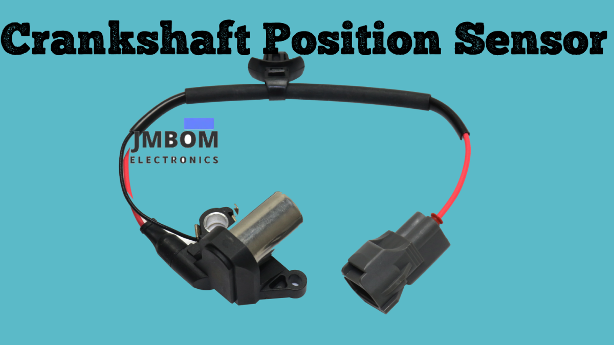
Crankshaft Position Sensor: Overview, Circuit Function& Comparison with Camshaft Sensors
Catalog
What Is a Crankshaft Position Sensor?How a Crankshaft Position Sensor WorksKey Components of a Crankshaft Position SensorTypes of Crankshaft Position SensorsHow to Test a Crankshaft Position Sensor Using a MultimeterHow to Reset a Crankshaft Position Sensor Without a ScannerCrankshaft Position Sensor vs. Camshaft Position SensorSymptoms of a Faulty Crankshaft Position Sensor (CPS)Common Causes of CPS FailureReplacing a Crankshaft Position SensorAdvantages and Disadvantages of Crankshaft Position SensorsApplications of Crankshaft Position SensorsConclusionCrankshaft Position Sensor FAQRelated ArticlesModern vehicles rely heavily on various sensors to monitor performance and relay critical information to the ECU (Engine Control Unit) or driver. Based on sensor data, the ECU can adjust systems to improve efficiency, performance, and safety. These sensors help monitor parameters such as engine health, oil pressure, temperature, emissions, vehicle speed, and more. Common automotive sensors include those for oxygen levels, airflow, throttle position, engine knock, voltage, MAP, camshaft position, crankshaft position, airbags, and parking assistance.This article focuses on the crankshaft position sensor—exploring its functionality, operation, types, and how it compares to the camshaft position sensor.
What Is a Crankshaft Position Sensor?
A crankshaft position sensor is an essential component in a vehicle’s engine management system. It tracks key engine variables such as the crankshaft’s position and rotational speed. It plays a vital role in determining ignition timing, engine RPM, and synchronizing fuel injection.
This sensor replaces the need for manually setting the distributor timing by automatically handling ignition and fuel delivery timing. Working alongside the camshaft position sensor, it helps the ECU identify the correct firing cylinder, activate the appropriate ignition coil, and control the sequence of fuel injection.
By detecting the crankshaft’s position through a magnetic or ferromagnetic encoder wheel attached to the shaft, the sensor sends real-time data—such as RPM and shaft position—to the ECU. The engine control unit uses this data to precisely manage ignition timing, fuel injection, and other vital engine operations.
How a Crankshaft Position Sensor Works
The crankshaft position sensor functions by tracking the crankshaft’s position and rotational speed, supplying vital data to the ECU (Engine Control Unit). This enables precise control over fuel injection and ignition timing, resulting in smoother engine performance and improved fuel efficiency.
By monitoring the crankshaft’s rotation, the sensor helps the ECU determine the engine’s speed and the crankshaft’s exact angular position.
Typically, the crankshaft position sensor is installed close to a reluctor ring or toothed wheel mounted on the crankshaft. As the crankshaft spins, the teeth or notches on the wheel move past the sensor, generating a signal that the ECU interprets. This signal is crucial for synchronizing ignition and fuel delivery with the engine's cycle, ensuring optimal operation.
Key Components of a Crankshaft Position Sensor
A crankshaft position sensor system consists of several core components:
Reluctor Ring or Toothed Wheel
This is a disk or ring with evenly spaced teeth or slots that is fixed to the crankshaft. As the crankshaft rotates, these teeth pass by the sensor, generating pulses used to detect position and speed.
Stationary Sensor (Magnetic or Optical)
Positioned next to the reluctor ring, this sensor can be based on magnetic or optical technology. It detects changes caused by the passing teeth and converts them into an electrical signal.
Electronic Circuitry
This part processes the raw signals from the sensor and relays clean, usable data to the ECU for real-time engine management.
Types of Stationary Sensors
Crankshaft position sensors typically use one of three types of stationary sensing technologies: magnetic, Hall-effect, or optical sensors. Each operates on a different principle, as described below:
Magnetic Sensors
Magnetic sensors consist of a magnet and a coil. As the toothed wheel rotates, its teeth interrupt the magnetic field, causing a variation in voltage across the coil. This voltage signal is then transmitted to the ECU for processing.
Hall-Effect Sensors
These sensors use a Hall-effect element that generates a voltage output based on the strength of the magnetic field. When the crankshaft rotates and the teeth pass by the sensor, they disturb the magnetic field, causing changes in the Hall sensor’s output. This signal is then relayed to the ECU for determining position and speed.
Optical Sensors
Optical sensors feature a light source and a photodetector. As the toothed wheel spins, the passing teeth interrupt the light beam, creating a signal pattern. This pattern is interpreted by the ECU to determine the crankshaft’s position.
Role of the Electronic Circuitry
The electronic circuitry receives the raw signal from the sensor (whether magnetic, Hall, or optical), refines it, and sends a clean, accurate signal to the ECU. This ensures the ECU receives consistent and precise data for real-time engine control.
Crankshaft Position Sensor Circuit
The circuit diagram for a crankshaft position sensor is illustrated below.
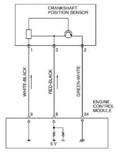
Crankshaft Position Sensor Circuit
Power is supplied to the crankshaft position sensor from pin 9 of the Engine Control Module (ECM). The sensor’s ground connection (terminal 2) is linked to pin 24 of the ECM.
A regulated 5V signal is provided to the sensor’s output terminal from a designated pin on the ECM. The sensor generates a pulse signal each time the output terminal toggles between open and ground states.
How the Circuit Works
The crankshaft position sensor monitors the angular position of the crankshaft (or individual cylinders) and converts this mechanical data into a series of electrical pulse signals. These pulses are then sent to the ECM for processing.
While the engine is running, the sensor continuously outputs these pulse signals. During engine startup (cranking), the ECM checks whether the signal is being received from the crankshaft sensor. This input is critical for the ECM to properly manage ignition timing and fuel injection sequences.
Types of Crankshaft Position Sensors
Crankshaft position sensors come in several different types, each based on a unique sensing principle. The most common types include inductive, Hall-effect, magnetoresistive, and optical sensors, as outlined below:
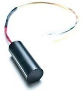
Inductive Sensors
Also known as variable reluctance sensors, these use a permanent magnet and coil to detect changes in a magnetic field caused by the teeth or notches on a toothed wheel mounted to the crankshaft or harmonic balancer. As the wheel spins and teeth pass by the sensor, the changing magnetic field induces a voltage signal.These sensors are passive devices, meaning they do not require an external power supply.
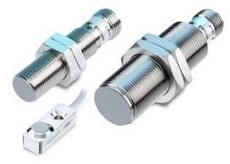
Inductive Sensors
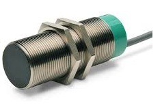
Hall-Effect Sensors
Hall-effect sensors work on the principle where a magnetic field generates a voltage across a semiconductor. Unlike inductive types, Hall sensors require a power supply and produce a digital square wave output to indicate the presence or absence of a tooth.These sensors can also detect static magnetic fields, making them useful even at low or zero speed.
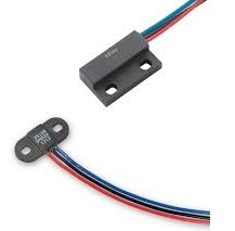
Hall Effect Sensor
Magnetoresistive Element Sensors
These sensors use a magnetoresistive element whose electrical resistance changes in response to a magnetic field. This allows them to detect both dynamic and static magnetic fields.
They offer improved sensitivity and resolution compared to standard Hall-effect sensors.
Magnetoresistive Element Sensor
Optical Sensors
Optical crankshaft sensors use a light source (usually an LED) and a photodetector to read slotted discs or reflective marks on a rotating shaft. As the shaft turns, the light beam is either blocked or allowed to pass, creating a signal pattern that represents the crankshaft’s position.
These sensors offer high precision and are suitable for both low-speed and high-speed applications. However, they require a clean optical path for accurate readings.
Optical Sensor
How to Test a Crankshaft Position Sensor Using a Multimeter
You can follow the steps below to test a Crankshaft Position (CKP) Sensor using a standard multimeter:
1. Disconnect the CKP Sensor
First, disconnect the sensor to avoid signal interference from other components.
- Locate the CKP sensor — typically mounted near the flywheel or crankshaft pulley.
- Carefully unplug the electrical connector. Depending on your vehicle, you may need to remove a protective cover or use a tool to release the connector latch.
2. Set Up the Multimeter
To begin testing, you'll need a multimeter that can measure resistance and voltage.
- Set the multimeter to the ohm (Ω) setting for resistance testing.
- Connect the probes to the appropriate terminals on the sensor.
3. Resistance Test
This checks whether the sensor coil is functioning correctly.
- Touch the multimeter leads to the sensor terminals.
- Observe the resistance reading. The exact value may vary depending on the sensor model and ambient temperature.
- Compare the reading to your vehicle manufacturer’s specifications. If the reading is out of range, the sensor may be faulty and should be replaced.
4. Voltage Test
This test verifies whether the sensor is generating the correct signal while the engine is running.
- Switch the multimeter to voltage mode (AC or DC depending on sensor type).
- Connect the multimeter probes to the sensor terminals.
- Start the engine to simulate crankshaft rotation.
- Monitor the voltage output on the multimeter. If the voltage reading is inconsistent or outside the expected range, the sensor may be defective.
5. Visual Inspection
Inspect the CKP sensor for any obvious damage, such as:
- Cracked housing
- Corrosion
- Loose or frayed wires If you see physical damage, it’s best to replace the sensor.
6. Reconnect the Sensor
After testing:
- Align the sensor’s connector with the plug on the wiring harness.
- Push it gently but firmly until it clicks into place.
- Ensure the connection is secure and tight.
How to Reset a Crankshaft Position Sensor Without a Scanner
While using a scanner is the recommended method to reset or recalibrate the crankshaft position sensor, there is a temporary workaround you can try if a scanner is not available:
Understand the Role of the CKP Sensor
The crankshaft position sensor helps the ECU calculate timing and performance parameters. A sensor or ECU issue may throw these values off balance.
Temporary Reset Procedure (Without a Scanner)
- Restart the Engine Turn off the vehicle and restart it. Sometimes, this can prompt the ECU to reset and recalibrate sensor readings temporarily.
- Drive at a Steady Speed After restarting, drive the car at a consistent speed for a short distance.
- Idle the Engine Bring the vehicle to a stop, but keep the engine running (do not switch to neutral or turn off). Let the car idle for a few minutes, giving the ECU a chance to relearn sensor behavior.
⚠️ Note: This is a temporary fix and may not solve underlying sensor issues. For accurate diagnostics and long-term performance, using a diagnostic scanner to perform a crankshaft position sensor relearn procedure is highly recommended.
Crankshaft Position Sensor vs. Camshaft Position Sensor
The crankshaft position sensor and the camshaft position sensor serve distinct but complementary roles in engine management:
- The crankshaft position sensor measures the rotation speed and position of the crankshaft.
- The camshaft position sensor monitors the exact position of the camshaft.
While both sensors are essential for engine timing, they serve different purposes:
- The crankshaft sensor helps determine ignition timing and piston position.
- The camshaft sensor assists in synchronizing the fuel injection and determining which cylinder is on its power stroke.
Together, they ensure precise control of ignition and fuel delivery, which is crucial for optimal engine performance, fuel efficiency, and emissions control.
| Crankshaft Position Sensor | Camshaft Position Sensor |
| The Crank position sensor is generally placed in the crankcase above the toothed wheel of the crankshaft. | The Camshaft position sensor is generally placed in line through the toothed wheel above the camshaft end. |
| It monitors crankshaft revolution and TDC (top-dead-center) position | This sensor monitors the camshaft revolution & valve position. |
| This sensor provides the ECU (Engine Control Unit ) with the necessary data for fuel injection timing, engine speed calculations & ignition timing,. | It helps the ECU synchronize fuel injection & ignition timing through the specific cylinder firing order & valve timing. |
| This sensor is can be found close to the flywheel (or) crankshaft pulley, frequently in the timing cover (or) near the base of the engine block. | It is located close to the camshaft (or) camshaft pulley, frequently on the head of cylinder otherwise timing cover. |
| Essential for engine starting and smooth operation. | Ensures proper valve timing for efficient engine performance. |
| The reluctor wheel speed of this sensor is double that of the camshaft reluctor wheel. | The reluctor wheel works at half of the crankshaft speed. |
| Its engine needs two crankshaft position sensors. | This sensor’s engines need a maximum of four camshaft position sensors. |
| The crankshaft position sensor falls short because of the electrical issues and overheating. | This sensor fails because of water damage, wear & tear, etc. |
Symptoms of a Faulty Crankshaft Position Sensor (CPS)
When the crankshaft position sensor starts to fail, it can trigger several noticeable issues, including:
- Check Engine Light On The most common early warning sign. The ECU will usually store a trouble code when it detects an issue with the sensor.
- Hard Starting or Failure to Start A faulty CPS may prevent the ECU from receiving accurate crankshaft data, causing the engine to crank without starting or start with delays.
- Engine Stalling or Cutting Out The engine may suddenly stall or shut off while driving, especially at higher speeds—posing a serious safety risk.
- Rough Idling or Misfiring Incorrect timing due to a bad sensor can lead to engine misfires, uneven idle, or vibrations while driving or idling.
- Increased Fuel Consumption When the ECU lacks correct timing input, it can lead to inefficient fuel injection, causing a noticeable drop in fuel economy.
- Unstable Acceleration The vehicle may hesitate or fail to accelerate smoothly, making driving unpredictable.
- Tachometer Malfunction The engine may crank, but the RPM gauge remains static, indicating a possible signal loss from the CPS.
- Backfiring or Hesitation In severe cases, engine timing errors may lead to backfiring or hesitation under load.
Common Causes of CPS Failure
Crankshaft position sensors operate under tough conditions, making them vulnerable to failure over time. Key causes include:
- Excessive Heat Exposure Constant exposure to engine heat can degrade internal components, causing the sensor to fail intermittently or completely.
- Vibration Damage Continuous vibration from the engine may loosen the sensor or break down its internal elements, leading to erratic signals.
- Wiring and Connector Issues Corroded terminals, damaged wiring, or loose connections can interfere with signal transmission to the ECU.
- Contamination from Oil or Debris Being located near the crankshaft, the sensor is exposed to potential contamination from oil leaks or engine debris, which can obstruct or damage its operation.
- Natural Wear Over Time Like many engine components, CPS sensors have a limited service life and may simply wear out after prolonged use.
Replacing a Crankshaft Position Sensor
If the CPS is diagnosed as faulty, replacement is typically the most effective solution. Here’s a general step-by-step overview:
- Disconnect the Battery Always disconnect the negative battery terminal before starting to avoid electrical shorts or shocks.
- Locate the Sensor The CPS is usually found near the crankshaft—either on the front of the engine block, near the flywheel, or close to the transmission bell housing.
- Access the Sensor Depending on your vehicle’s layout, you may need to remove other components to reach the sensor.
- Remove the Faulty Sensor Unplug the electrical connector, unscrew the mounting bolts, and carefully remove the sensor.
- Install the New Sensor Position the new sensor in the same location, secure it with bolts, and ensure all electrical connections are tight and secure.
- Reconnect the Battery and Test Reconnect the battery and start the engine. If installed properly, the new CPS should eliminate issues like hard starting, rough idle, or engine stalling.
Advantages and Disadvantages of Crankshaft Position Sensors
✅ Advantages
- Precise Ignition and Fuel Timing Ensures accurate ignition timing and fuel injection, enhancing overall engine control.
- Improved Engine Performance Allows for smoother and more responsive engine operation under various conditions.
- Better Fuel Economy Helps the ECU optimize combustion, leading to reduced fuel consumption.
- Reduced Emissions Accurate timing control minimizes unburned fuel, contributing to lower pollutant output.
- Detection of Misfires Enables the ECU to identify and prevent misfires early, reducing engine wear.
- Supports Stop-Start Technology Assists in smooth engine restarting, improving urban driving efficiency and regulatory compliance.
❌ Disadvantages
- Starting Problems A malfunctioning sensor may prevent proper engine start or delay cranking.
- Unexpected Stalling Engine may shut down suddenly if the sensor fails or sends erratic signals.
- Rough Idling and Misfiring Inaccurate readings can lead to unstable engine operation, vibrations, or misfires.
- Poor Fuel Efficiency Faulty signals can cause incorrect fuel injection timing, increasing consumption.
- Acceleration Issues Delayed or sluggish throttle response can occur due to incorrect crankshaft position feedback.
- Illuminated Check Engine Light Faulty sensor behavior often triggers diagnostic trouble codes.
- Cost of Replacement Depending on vehicle type and sensor location, replacement may be labor-intensive and costly.
- Vulnerability to Environmental Conditions Exposed to high heat, oil, dirt, and vibration, which may lead to failure or degraded accuracy.
- Signal Interruption from Damaged Wiring Wiring issues can lead to loss or distortion of sensor signals, disrupting engine control.
Applications of Crankshaft Position Sensors
- Crankshaft Monitoring Measures the exact position and rotational speed of the crankshaft—critical for engine synchronization.
- Ignition Control Helps the ECU determine precise spark timing for optimal combustion.
- Fuel Injection Regulation Provides timing input for accurate fuel delivery, improving efficiency and power output.
- Engine Speed Monitoring (RPM) Supplies real-time RPM data to the ECU for various control functions.
- Emissions Reduction Assists in combustion management to reduce exhaust pollutants.
- Engine Start/Stop Systems Key to managing start-stop operations in modern vehicles for fuel saving and reduced idling.
- Misfire Detection Enables identification of misfires to prevent engine damage and maintain emissions compliance.
Conclusion
The crankshaft position sensor is a crucial component that monitors the crankshaft’s position and speed, sending this data to the ECU to manage ignition timing, fuel injection, and overall engine performance. A properly functioning CKP sensor helps ensure smooth operation, better fuel efficiency, and reduced emissions.
Crankshaft Position Sensor FAQ
❓ What happens if the crankshaft position sensor goes bad?
A faulty crankshaft position sensor can lead to several issues, including:
- Engine misfires: The ECU may receive incorrect or no signal, leading to mistimed ignition.
- Rough idling: Unstable engine operation, often felt as vibrations or stalling at idle.
- Poor acceleration: Timing and fuel delivery may be thrown off, causing hesitation or sluggish response.
- Check engine light: A malfunctioning sensor often triggers a warning light and stores a diagnostic trouble code.
❓ Can a bad crankshaft sensor cause a car to stop running?
Yes. If the crankshaft sensor fails or provides inaccurate signals, the ECU cannot properly control ignition and fuel injection. This may result in:
- Engine stalling while driving.
- Sudden shut-off, especially under load or at idle.
- Hard starting or complete failure to start.
❓ What happens if the crankshaft breaks while driving?
A broken crankshaft is a critical engine failure. Since it converts piston motion into rotational energy:
- The engine will lose power instantly.
- You may experience engine seizure or catastrophic damage.
- Repair typically requires a full engine rebuild or replacement.
❓ What causes a crankshaft position sensor error code (e.g., P0335)?
Several issues can trigger a crankshaft sensor-related code:
- Failed crankshaft position sensor
- Damaged reluctor ring (toothed wheel)
- Wiring issues (broken, corroded, or loose connectors)
- Faulty PCM/ECU (less common)
Symptoms often include:
- Illuminated check engine light
- Engine stalling or hesitation
- Misfires or starting problems
❓ Will disconnecting the battery reset the crankshaft position sensor?
Usually, no. Simply disconnecting the battery does not reset or recalibrate the crankshaft position sensor. Some vehicles require a scanner or a specific relearn procedure after sensor replacement to ensure proper synchronization with the ECU.
❓ Will a car start with a bad crankshaft position sensor?
In many cases, no. A completely failed sensor means the ECU can't determine engine position or speed, so:
- The fuel injectors won’t fire properly.
- The spark plugs won’t ignite at the right time.
- The engine will crank but likely won’t start.
Related Articles
TPS7A26 LDO Regulator: Functionality and Key Applications
Guide to Low Dropout (LDO) Regulators and How They Work
ESP32-S3 Development Board: Pinout Diagram, Key Features, Technical Specs
DS18B20 Waterproof Temperature Sensor: Overview, Operation, and Common Uses
BAT54A Schottky Diode: Pinout and Common Uses
Infineon ILD8150E LED Driver IC Overview
LF353N Op-Amp Explained: Pinout, Features, and How It Works
ADXL335 Accelerometer Sensor: Pinout, Specs, Features, and How It Works
Engine Coolant Temperature Sensor: Overview, Function & Circuit Design

Amanda Miller
Amanda Miller is a senior electronics engineer with 6 years of experience. She focuses on studying resistors, transistors, and package design in detail. Her deep knowledge helps her bring innovation and high standards to the electronics industry.
Subscribe to JMBom Electronics !


