


Measuring Amplitude: A Practical Guide for Engineers
Catalog
What is Amplitude: From Basics to ApplicationsKey Points About Amplitude in Wave TheoryTheoretical Foundations of Amplitude MeasurementWaveform AnalysisMathematical Representation of AmplitudeFrequency and AmplitudePractical Guide to Measuring AmplitudeEssential Tools and EquipmentStep-by-Step Measurement ProcedureAdvanced Measurement TechniquesNavigating Common Challenges in Amplitude MeasurementImportance of Calibration and MaintenanceGuidelines for Calibration and MaintenanceJMBom Calibration Services: Meeting Your NeedsReal-World Applications: Amplitude in ActionAmplitude in TelecommunicationsAudio Engineering and AmplitudeConclusion: Amplify Your Engineering Expertise with JMBomFrequently Ask QuestionsRelated ArticlesPicture yourself developing cutting-edge satellite systems. Every component you build and every signal you monitor must be exact. Just one miscalculation could cause the satellite to lose contact with Earth.
In such high-stakes work, the amplitude of electronic signals plays a vital role, underscoring why accurate amplitude measurement is essential across the field of engineering.
In this guide, we’ll look at the many uses of amplitude measurement—from optimizing communication networks and designing durable systems to enhancing the performance of audio technology.
What is Amplitude: From Basics to Applications
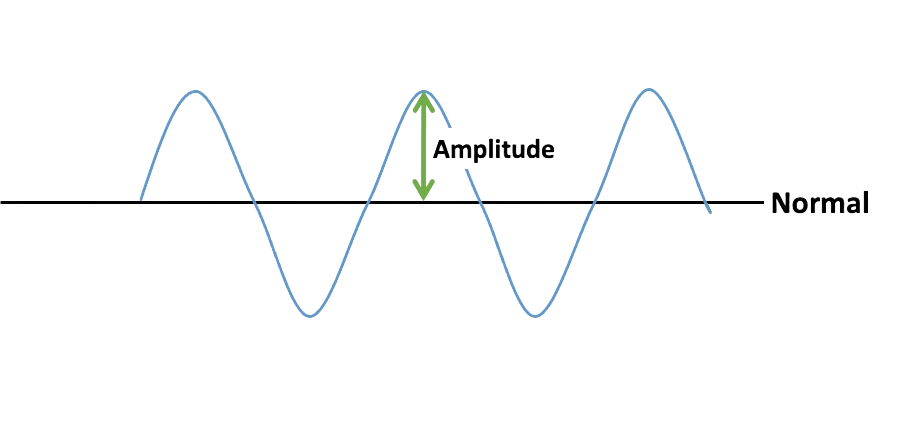
In wave theory, amplitude refers to the height of a wave measured from its resting point to its peak. In simple terms, it represents the strength or intensity of the wave.
You can picture waves like ripples moving across a pond or sound waves spreading out from a speaker. The amplitude is the distance between the baseline of the wave (its rest position) and its highest point (the crest) or lowest point (the trough).
To make this clearer, let’s use a simple diagram that illustrates amplitude in different types of waveforms.
Amplitude is a key factor in defining the strength and quality of a signal. In telecommunications, a signal with greater amplitude carries more power and can reach longer distances. In audio engineering, amplitude directly affects loudness: higher amplitude produces louder sounds, while lower amplitude creates softer ones.
Key Points About Amplitude in Wave Theory
- Definition: Amplitude is the maximum displacement of a wave measured from its equilibrium position.
- Units of measurement: Typically expressed in decibels (dB) for sound waves, or volts when referring to electrical signals.
- Impact on signal quality: A higher amplitude can enhance signal strength and clarity, though excessive amplitude may cause distortion if not controlled.
- Role across different wave types: In sound waves, amplitude determines loudness; in light waves, it affects brightness; and in electrical signals, it reflects signal strength.
- Practical use in engineering: Engineers frequently adjust amplitude in fields like signal processing, audio design, and broadcasting to achieve specific performance goals.
Recognizing the importance of amplitude—and how it behaves across various types of waves—is essential for engineers and scientists working with sound, light, electricity, or any other waveform.
Theoretical Foundations of Amplitude Measurement
Measuring amplitude is fundamental to understanding and applying wave theory, forming a critical part of many scientific and engineering fields.
To fully grasp amplitude, it’s important to study waveform analysis, since different waveforms display unique amplitude characteristics.
Waveform Analysis
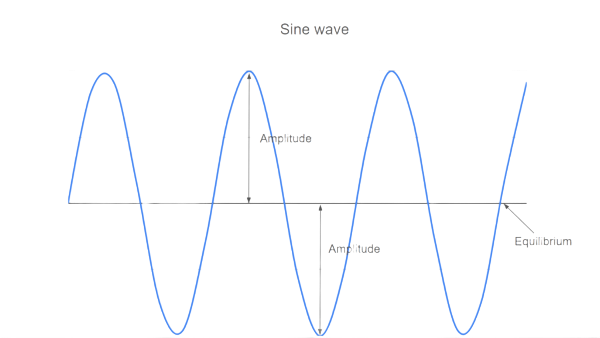
Sine Waves
- Description: A smooth, continuous oscillation that lies at the heart of wave theory.
- Amplitude: The peak value of the wave, measured from the center line (equilibrium) to its crest.
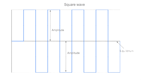
Square Waves
- Description: Defined by sharp transitions between high and low states, producing a square-like shape.
- Amplitude: The maximum deviation from the center line, equal in both positive and negative directions.
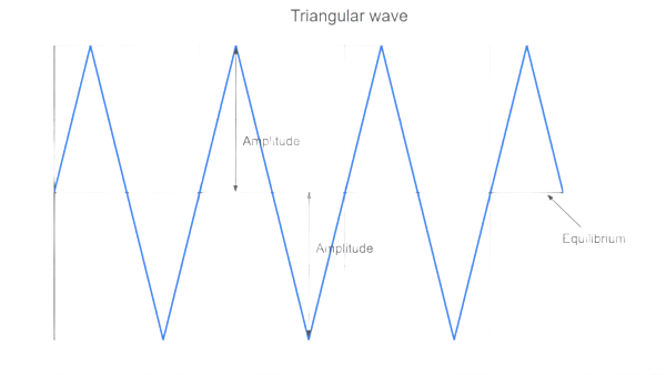
Triangle Waves
- Description: A waveform with linear rises and falls, creating a triangular profile.
- Amplitude: Like sine waves, the peak distance from the center line to the highest or lowest point.
Sawtooth Waves
- Description: Shaped like the teeth of a saw, with a gradual rise followed by a sharp drop (or the reverse).
- Amplitude: Determined by the extreme values reached before the abrupt change in direction.
Pulse Waves
- Description: Similar to square waves but with uneven durations at the high and low levels.
- Amplitude: The maximum value attained during the pulse.
Waveform Comparisons
| Waveform Type | Shape Description | Amplitude Description |
|---|---|---|
| Sine | Smooth, periodic oscillation | Peak value from the center line to the crest |
| Square | Sudden shifts between high and low states | Maximum value, equal in both positive and negative directions |
| Triangle | Linear rise and fall forming a triangular shape | Peak distance from center line to highest or lowest point |
| Sawtooth | Gradual rise with a sharp drop (or the reverse) | Defined by the extreme values before the sudden change |
| Pulse | Unequal time spent at high and low states | Maximum value reached during the pulse |
This comparison highlights how amplitude behaves differently across waveforms, each with unique features and specialized applications.
Mathematical Representation of Amplitude
Mathematical models are essential for accurately quantifying and analyzing amplitude. Depending on the context, engineers and scientists use different representations:
- Peak Amplitude (A): The maximum displacement a waveform reaches (positive or negative) from its equilibrium point.
- Peak-to-Peak Amplitude (App): The total vertical range of the waveform, measured from its maximum positive value to its maximum negative value. This is especially important in applications such as AC circuit analysis.
- Root-Mean-Square (RMS) Amplitude: The effective or “power equivalent” value of a waveform, representing the DC-equivalent level. It is calculated as the square root of the average of the squared values, making it highly relevant for power calculations.
Example Calculations
Sine Wave
- Peak Amplitude: A=max(sinθ)A = \max(\sin \theta)A=max(sinθ)
- Peak-to-Peak Amplitude: App=2AA_{pp} = 2AApp=2A
- RMS Amplitude: ARMS=A2A_{RMS} = \frac{A}{\sqrt{2}}ARMS=2A
Square Wave
- Peak Amplitude: A=max(square wave value)A = \max(\text{square wave value})A=max(square wave value)
- Peak-to-Peak Amplitude: App=2AA_{pp} = 2AApp=2A
- RMS Amplitude: ARMS=AA_{RMS} = AARMS=A (constant amplitude throughout)
Triangle Wave
- Peak Amplitude: A=max(triangle wave value)A = \max(\text{triangle wave value})A=max(triangle wave value)
- Peak-to-Peak Amplitude: App=2AA_{pp} = 2AApp=2A
- RMS Amplitude: ARMS=A3A_{RMS} = \frac{A}{\sqrt{3}}ARMS=3A
These mathematical models form the foundation for waveform analysis, enabling precise measurement, accurate interpretation, and effective application across engineering and scientific fields.
Frequency and Amplitude
The relationship between frequency and amplitude is central to understanding signal behavior across disciplines such as audio engineering, telecommunications, and electrical systems. Although frequency and amplitude are separate properties, the way they interact has a major influence on how signals perform and are perceived.
- Frequency: The number of cycles a waveform completes in a given time, measured in Hertz (Hz). In audio, frequency defines pitch, while in electronics it reflects the rate of oscillation.
- Amplitude: The measure of a signal’s strength or intensity. In sound, it affects loudness, and in electrical signals, it indicates power or voltage level.
Combined Effects
- Perception of sound: In audio, higher frequencies are heard as higher-pitched tones, while amplitude controls volume. A bass note (low frequency) and a treble note (high frequency) may sound equally loud if their amplitudes are the same.
- Signal transmission: In telecommunications, frequency determines data-carrying capacity—higher frequencies can carry more information but are more prone to interference. Amplitude affects range and signal strength, though excessive amplitude may introduce distortion or noise.
- Power distribution: In electrical systems, both amplitude and frequency influence transmitted power. Larger amplitudes mean greater power, but this must be matched with the correct frequency to maximize efficiency and protect components.
- Harmonic content: Frequency sets the fundamental tone, while harmonics—integer multiples of that base frequency—shape the timbre or color of a sound in music and audio processing.
In short, frequency defines how fast a signal oscillates, while amplitude determines how strong it is. Their interplay forms the foundation of signal behavior, making it essential for engineers and scientists to carefully balance both when designing effective systems and technologies.
Practical Guide to Measuring Amplitude
In engineering and scientific practice, accurate amplitude measurement is essential. Selecting the right instrument not only improves precision but also ensures efficiency and reliability across applications—from electronic circuit design to acoustics and telecommunications.
Below, we’ll look at the core tools used for amplitude measurement, outlining their functions and where they are most effective.
Essential Tools and Equipment
Oscilloscopes
- Role: A fundamental tool for observing electronic signals in real time. Oscilloscopes display amplitude against time, giving a clear picture of waveform shape and behavior.
- Use cases: Detailed analysis of waveforms, including frequency, distortion, and amplitude in circuit testing.
Multimeters
- Role: Compact instruments that measure voltage, current, and resistance. While less detailed than oscilloscopes, they provide quick and reliable amplitude measurements.
- Use cases: Everyday tasks such as checking battery voltage, testing continuity, or diagnosing simple circuit problems.
Spectrum Analyzers
- Role: Specialized devices that show how amplitude is distributed across frequencies, offering insights into a signal’s spectral components.
- Use cases: Crucial for radio frequency (RF) work, wireless communication systems, and audio signal analysis.
Function Generators
- Role: Primarily designed to generate test signals of varying amplitude, frequency, and waveform, but also useful for calibration and system testing.
- Use cases: Commonly used to simulate input signals for testing amplifiers, filters, and other electronic equipment.
Comparison of Devices
| Device | Primary Function | Key Features | Ideal Use Case |
|---|---|---|---|
| Oscilloscope | Visualize waveforms | Real-time waveform display, detailed signal analysis | Electronic circuit testing, signal analysis |
| Multimeter | Measure voltage/current | Portable, easy to use | Basic diagnostics, simple electrical tests |
| Spectrum Analyzer | Analyze frequency spectrum | In-depth frequency and amplitude distribution | RF systems, audio frequency analysis |
| Function Generator | Generate test signals | Adjustable frequency, amplitude, and waveform | Equipment testing, calibration, signal generation |
Each tool serves a unique role in amplitude measurement. The choice depends on the complexity of the signal being analyzed and the level of detail required—from quick voltage checks with a multimeter to deep frequency-domain insights with a spectrum analyzer.
Step-by-Step Measurement Procedure
Measuring amplitude depends on both the context and the equipment being used. The following general procedure applies to most situations:
- Select the appropriate tool – Choose an oscilloscope, multimeter, or another measurement device based on the level of detail required.
- Connect the device – Safely attach your measurement instrument to the signal source. For oscilloscopes, this usually means connecting the probe to the test point in the circuit.
- Configure the settings – Adjust the device according to the signal type. On an oscilloscope, for example, set the time base and voltage-per-division to match the expected amplitude and frequency.
- Observe the signal – View the waveform on the oscilloscope display or read the value directly from the multimeter.
- Record the measurement – Note the amplitude reading. On an oscilloscope, this may involve measuring the vertical distance from the centerline to the crest (peak amplitude) or from crest to trough (peak-to-peak amplitude).
- Repeat and verify – Take multiple measurements and calculate the average to improve accuracy.
Tips for Accuracy and Precision
- Ensure your measuring instrument is properly calibrated before use.
- Use high-quality probes and cables to minimize signal loss or distortion.
- Check that the bandwidth of your device matches or exceeds the frequency of the signal.
- Reduce external interference, such as electromagnetic noise or vibrations, that may affect accuracy.
- In noisy environments, use the averaging function (if available) on your instrument to obtain a more stable reading.
Advanced Measurement Techniques
In more complex applications, advanced methods of amplitude measurement become essential. These techniques allow for deeper insights and more accurate analysis when simple tools are not sufficient.
- Fast Fourier Transform (FFT) FFT is a mathematical technique that transforms a time-domain signal into its frequency-domain representation. By breaking a signal into its frequency components, FFT makes it possible to analyze the amplitude of each frequency within a complex waveform. This is widely used in audio processing, vibration monitoring, and telecommunications.
- Time-Domain Reflectometry (TDR) TDR is a diagnostic method used to analyze cables and transmission lines. By sending a short pulse through the line and measuring the reflected signal, TDR reveals impedance variations and locates faults. The amplitude of the reflected waveform provides valuable clues about the type and severity of the issue.
- Digital Signal Processing (DSP) DSP refers to a broad set of methods for analyzing and manipulating digital signals. Techniques such as filtering, modulation, and demodulation often rely on FFT for detailed frequency analysis. DSP underpins many modern technologies, including digital audio, wireless communications, and image processing.
These advanced techniques expand the scope of amplitude measurement, enabling engineers and scientists to perform highly precise and application-specific analyses. For professionals working in fields where signal integrity and accuracy are critical, mastering FFT, TDR, and DSP is indispensable.
Navigating Common Challenges in Amplitude Measurement
While amplitude measurement is fundamental in engineering and science, it is not without challenges. A range of factors—from external interference to equipment limitations—can impact accuracy and reliability. Recognizing these issues and applying the right solutions is key to obtaining dependable results.
1. Signal Interference
Interference can distort signals and lead to inaccurate amplitude readings. Identifying and mitigating interference is the first step toward precision.
Common Sources:
- Electromagnetic interference (EMI) from nearby electronic devices
- Radio frequency interference (RFI) from wireless transmitters
- Noise from power lines, especially in industrial settings
- Cross-talk between adjacent signal lines
Mitigation Strategies:
- Use shielded cables and proper grounding to reduce EMI
- Maintain distance or shielding from RFI sources
- Apply filters to isolate the desired frequency band
- Use twisted-pair cables and separate signal lines to minimize cross-talk
2. Equipment Limitations
Every measuring device has limits, and pushing beyond them compromises accuracy.
Key Considerations:
- Bandwidth and frequency range of the instrument
- Resolution and sensitivity levels
- Calibration status of the device
Strategies:
- Select equipment appropriate for the specific task
- Avoid exceeding the rated limits of the instrument
- Regularly calibrate and, when in doubt, consult manuals or expert guidance
3. Environmental Factors
External environmental conditions can also influence amplitude measurements.
Impacts:
- Temperature variations can change resistance values, altering signal strength
- High humidity may cause condensation or short circuits
- Atmospheric pressure shifts can affect highly sensitive instruments
Compensation Techniques:
- Use temperature-compensated equipment where possible
- Maintain a stable, dry, controlled environment for testing
- Account for environmental variations in calculations or rely on equipment with built-in compensation features
Conclusion
By anticipating and addressing these common challenges—interference, equipment constraints, and environmental effects—you can significantly improve both the accuracy and reliability of amplitude measurements.
Calibration and Maintenance of Measuring Equipment
The accuracy and reliability of amplitude measurements depend heavily on the precision of instruments such as oscilloscopes, multimeters, and signal analyzers. Regular calibration and maintenance are essential to keep these tools performing optimally and producing trustworthy results. Calibration aligns your equipment’s readings with established standards, ensuring measurement accuracy and consistency.
Importance of Calibration and Maintenance
- Accuracy and reliability: Calibration guarantees that your measurements correspond with recognized standards, which is critical in fields requiring high precision like scientific research, manufacturing, and quality assurance.
- Regulatory compliance: Many industries mandate routine calibration of measurement devices to meet safety and quality regulations.
- Error prevention: Routine maintenance and calibration help detect and correct problems early, preventing significant errors or equipment breakdowns.
Guidelines for Calibration and Maintenance
- Calibration frequency The ideal calibration interval depends on how frequently and under what conditions the equipment is used. Environments demanding high precision or heavy usage call for more frequent calibration. A common recommendation is to calibrate instruments at least once a year. Always consult manufacturer guidelines and relevant industry standards for specific intervals.
- When calibration is needed If measurements become inconsistent or deviate unexpectedly. After physical impacts or damage to the equipment (e.g., dropping or bumping an oscilloscope). Following significant environmental changes, such as temperature fluctuations. If the device has been heavily used without calibration for a long period.
JMBom Calibration Services: Meeting Your Needs
JMBom offers comprehensive calibration solutions tailored to diverse professional requirements across industries. Their commitment to precision and multi-brand support helps maintain your instruments’ accuracy and reliability.
- Precise Calibration for Every Specification Each instrument’s specifications, options, and details are calibrated to ensure your system operates exactly as intended.
- One-Stop Calibration for All Brands JMBom supports calibration services not only for their own products but also for other brands. You can schedule calibrations every 6, 12, 24, or 36 months to keep all your test equipment in peak condition.
- Standards Lab Calibration for Accuracy By comparing your devices to primary or reference standards, JMBom guarantees the highest accuracy levels necessary for critical applications.
- Antenna Calibration for Compliance Their services ensure compliance with standards, delivering SI-traceable results suitable for applications ranging from radio and radar to EMI/EMC testing.
- Extended Service for Instrument Longevity JMBom supports legacy instruments and long-term programs, allowing a smooth transition to new technologies at your own pace.
- Global and Local ISO/IEC 17025 Accreditation JMBom’s calibration labs are accredited by various local and global bodies—including JCSS, CNAS, UKAS, and ANAB—ensuring compliance with international and regional requirements.
Regular calibration and maintenance through JMBom’s expert services go beyond routine checks—they are a vital investment in your equipment’s accuracy, reliability, and lifespan. Leveraging JMBomt’s advanced technology and expertise ensures your instruments consistently deliver precise results, supporting the success and safety of your projects and research.
Real-World Applications: Amplitude in Action
Amplitude is far more than a theoretical concept—it plays a crucial role across a wide range of practical applications. From ensuring the clarity of a phone call to enabling precise medical diagnostics, amplitude’s impact is both broad and essential.
Understanding how amplitude functions in different fields highlights its universal significance across industries.
Amplitude in Telecommunications
In telecommunications, amplitude is key to defining signal strength. A higher amplitude means a stronger signal, which is vital for clear voice and data transmission over long distances.
Technologies like amplitude modulation (AM) work by varying the amplitude of a carrier wave in proportion to the information signal. However, signals with high amplitude are often more susceptible to noise and interference, requiring careful control to maintain quality.
Effective amplitude measurement and management are critical for reliable communication systems—whether in mobile networks, satellite links, or broadcasting.
Audio Engineering and Amplitude
In audio engineering, amplitude directly influences how loud or soft a sound is perceived. Whether in recording studios, concert venues, or home audio setups, controlling amplitude is essential to achieving the desired sound quality.
Sound engineers adjust amplitude levels to balance different instruments or vocal tracks, ensuring clarity without distortion.
Beyond mixing, precise amplitude control plays a vital role in sound design, helping create moods or effects for movies, video games, and other media.
Medical Equipment and Diagnostics
Amplitude measurement is also fundamental in medical technology, particularly in diagnostic and therapeutic devices.
For instance, in electrocardiograms (ECGs), the amplitude of the heart’s electrical signals provides valuable information about cardiac health.
In ultrasound imaging, the amplitude of sound waves determines the quality of images of internal organs and tissues. Accurate amplitude measurement and interpretation are critical for correct diagnosis and effective treatment planning.
Conclusion: Amplify Your Engineering Expertise with JMBom
Throughout this guide, we’ve delved into the complex world of amplitude measurement and its vital role across diverse engineering fields. From telecommunications and audio production to medical diagnostics, precise amplitude measurement and control are key to ensuring success and reliability in countless applications.
Remember the essentials: grasp the different forms of amplitude—peak, peak-to-peak, and RMS—and their practical uses; recognize the importance of tools like oscilloscopes and multimeters; and appreciate advanced techniques such as FFT and TDR.
We’ve also covered the challenges posed by signal interference and environmental factors, as well as the critical need for regular calibration and maintenance—expertly supported by JMBom’s industry-leading services.
By applying these insights, you’re not just understanding wave theory—you’re enhancing your ability to innovate, optimize, and excel in your engineering projects.
With the right knowledge, cutting-edge tools, and trusted partners like JMBom, you’re fully equipped to unlock the true potential of your work.
“Mastering amplitude measurement isn’t just about understanding waves; it’s about unlocking new possibilities in your engineering journey.”
Frequently Ask Questions
What can you use to measure amplitude?
- Oscilloscopes – An oscilloscope is essential for viewing and measuring the waveform of electronic signals. It displays amplitude against time, allowing you to observe signal behavior in real time.
How can you calculate amplitude?
- The symbol for amplitude is A.
- For a periodic function with a bounded range, amplitude equals half the distance between the maximum and minimum values.
- In simple terms, it’s the distance from the centerline (equilibrium) to a peak or trough.
- x=Asin(ωt+ϕ)orx=Acos(ωt+ϕ)x = A \sin(\omega t + \phi) \quad \text{or} \quad x = A \cos(\omega t + \phi)x=Asin(ωt+ϕ)orx=Acos(ωt+ϕ)
How do you measure maximum amplitude?
- In seismology, maximum amplitude is measured using a seismogram.
- First, the time difference between the P-wave and S-wave recordings is used to determine distance.
- Then, the largest single amplitude recorded on the seismogram is located, and a line is drawn between the amplitude scale and the distance scale to calculate it.
What is the current amplitude?
- Current amplitude (also called magnitude or intensity) is the vertical distance between the highest and lowest points of an electrical wave.
- It is typically measured in milliamperes (mA).
Which instrument is used to measure the amplitude of sound?
- The decibel (dB) scale is used to measure the amplitude of sound.
- Amplitude in sound represents the displacement or variation of a wave from its resting value, which directly affects how loud we perceive the sound to be.
Related Articles
What is a Fuse: Different Types and Its Applications
How to Use a Transistor as a Switch
How Photoresistors Work, Types, and Common Uses
Various Types of Sensors Used in Modern Vehicles
Essential Impedance Formula Handbook for Electrical Engineers
Guide to Potentiometers and How to Connect Them
Guide to Series and Parallel Circuits

Christopher Anderson
Christopher Anderson has a Ph.D. in electrical engineering, focusing on power electronics. He’s been a Senior member of the IEEE Power Electronics Society since 2021. Right now, he works with the KPR Institute of Engineering and Technology in the U.S. He also writes detailed, top-notch articles about power electronics for business-to-business electronics platforms.
Subscribe to JMBom Electronics !


