


What is DC Voltage?
Catalog
What is DC Voltage?DC Voltage SymbolsIEC DC Power Circuit Wire Color CodesMethods of Reducing DC VoltageReducing DC Voltage with ResistorsHow to Increase DC VoltageMeasuring DC VoltageCommon Uses of DC VoltageDC Voltage Symbol (⎓) and Its PurposeReading DC Voltage MeasurementsWhy DC Voltage Is ImportantConclusionRelated ArticlesDirect current voltage, often called DC voltage, is a basic principle in electricity and electronics. Unlike alternating current (AC), which switches direction back and forth, DC voltage moves continuously in a single direction. You’ll find DC voltage used in many areas, from everyday electronic devices to large-scale industrial equipment. Knowing how DC voltage works is useful for diagnosing electrical issues and choosing the right instruments for measurement.
What is DC Voltage?
DC voltage stands for Direct Current Voltage. It refers to a type of voltage that keeps the same polarity, meaning it always pushes current in one fixed direction through a circuit.
There are two main forms of DC voltage:
- Constant DC voltage – where both the magnitude and polarity stay unchanged.
- Variable DC voltage – where the magnitude changes over time, but the polarity remains the same.
DC voltage is commonly supplied by sources such as cells, batteries, or DC generators. Since its polarity never switches, DC voltage has a frequency of zero.
DC Voltage Symbols
In electrical and electronic circuits, the symbol used for DC voltage depends on the type of source. For example, cells, batteries, and other DC voltage sources each have their own standard symbols, as shown in Figure-1.

DC Voltage Wire Color Codes
In electrical wiring, different wire colors are used to indicate polarity. This color coding helps simplify installation and makes maintenance work safer and easier. For DC wiring, there are two main color code standards in use: IEC DC Power Circuit Wire Color Codes and US DC Power Circuit Wire Color Codes.
IEC DC Power Circuit Wire Color Codes
IEC stands for International Electrotechnical Commission, which sets global standards for DC power wiring. According to the IEC standard, the wire colors are as follows:
| DC System | Wire Name & Label | Wire Color |
|---|---|---|
| Ground or Earth | PE | Green-Yellow Stripes |
| Two-wire ungrounded DC circuit | Positive “L+” | Brown |
| Negative “L-” | Grey | |
| Two-wire grounded DC circuit | Positive (with negative grounded) “L+” | Brown |
| Negative (with negative grounded) “M” | Blue | |
| Positive (with positive grounded) “M” | Blue | |
| Negative (with positive grounded) “L-” | Grey | |
| Three-wire grounded DC circuit | Positive “L+” | Brown |
| Mid-Wire (Center tap) “M” | Blue | |
| Negative “L-” | Grey |
US DC Power Circuit Wire Color Codes
Another standard for DC wiring is defined by the US National Electrical Code (NEC). Unlike the IEC system, the NEC does not specify wire color codes for ungrounded DC systems, as these are considered unsafe to use under US regulations.
The NEC recommendations for grounded DC wiring are outlined in the table below:
| DC System | Wire Name & Label | Wire Color |
|---|---|---|
| Protective Ground or Earth | PG | Bare conductor, Green, or Green-Yellow Stripes |
| Two-wire ungrounded DC system | Positive “L+” | No official recommendation (commonly Red) |
| Negative “L-” | No official recommendation (commonly Black) | |
| Two-wire grounded DC system | Positive (with negative grounded) “L+” | Red |
| Negative (with negative grounded) “N” | White | |
| Positive (with positive grounded) “N” | White | |
| Negative (with positive grounded) “L-” | Black | |
| Three-wire grounded DC system | Positive “L+” | Red |
| Mid-wire “N” | White | |
| Negative “L-” | Black |
Methods of Reducing DC Voltage
In many cases, the DC voltage from a source needs to be reduced before it can be safely applied to a load. For instance, if you have a 9V battery but your LED lamp is rated for only 3V, the voltage must be lowered to avoid damaging the LED. This can be done using components such as resistors and diodes.
Reducing DC Voltage with Resistors
When resistors are connected in series, they create what’s called a voltage divider circuit. This circuit takes a single DC voltage and divides it into smaller voltage levels. By selecting the right resistor values, you can obtain the exact voltage needed for your load. An example of a voltage divider for reducing DC voltage is shown in Figure-2.
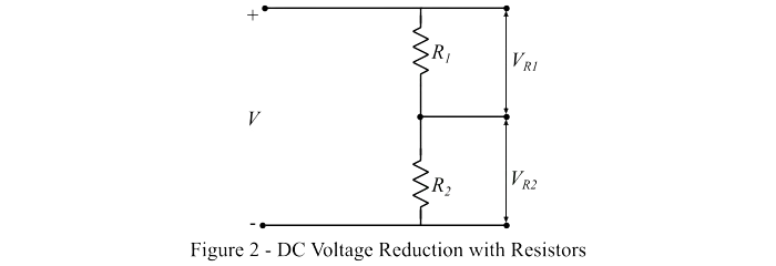
In this circuit, V represents the total input voltage. The voltages across the resistors R₁ and R₂ can be calculated using the following formulas:
VR1=VR1R1+R2
And,
VR2=VR2R1+R2
Using these two equations, we can determine the appropriate values of R₁ and R₂ to place in the circuit in order to achieve the desired DC voltage.
Reducing DC Voltage with Diodes
A diode is a one-way electronic component that allows current to flow only when it is forward biased. In this state, a small voltage drop occurs across the diode. For a standard silicon diode, this drop is about 0.6 V to 0.7 V, while for a germanium diode it is roughly 0.25 V to 0.3 V.
By connecting multiple diodes in series with the load, this voltage drop can be increased step by step, thereby reducing the effective voltage supplied to the load, as illustrated in Figure-3.
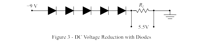
In the example shown in Figure-3, the 9V battery voltage is reduced to about 5.5V, while the remaining 3.5V is dropped across the diodes (assuming each diode has a forward voltage drop of 0.7V).
How to Increase DC Voltage
DC voltage can be increased using an electronic circuit called a DC-DC Power Converter or Boost Converter. A typical boost converter includes at least two semiconductor switching devices (such as diodes or transistors) along with an energy storage element, usually an inductor or capacitor.
Measuring DC Voltage
Some common methods for measuring DC voltage include:
- Using a DC voltmeter.
- Using a digital multimeter, which can measure both AC and DC voltages.
- Applying Ohm’s law (V = I × R), when the current and resistance values of the circuit are known.
Common Uses of DC Voltage
DC voltage is widely used in:
- Batteries – from small devices like remote controls to large systems such as electric cars.
- Solar energy systems – producing DC electricity from sunlight before converting it into AC for household use.
- Electronics and circuit boards – as most low-voltage electronic components run on DC power.
DC Voltage Symbol (⎓) and Its Purpose
The DC voltage symbol (⎓) is often seen in circuit diagrams and measurement tools. It shows a solid line (―) above three short dashes, making it easy to distinguish from the AC symbol (∿).
On tools like a digital multimeter (DMM), the DC voltage setting is usually marked as V⎓. Recognizing this symbol helps ensure correct measurements and troubleshooting of electrical parts.
Reading DC Voltage Measurements
When measuring DC voltage:
- The reading will show in volts (V), millivolts (mV), or another unit depending on the meter’s settings.
- A positive reading means the red probe is on the higher potential side.
- A negative reading simply means the probes are reversed, but the voltage value itself stays the same.
Why DC Voltage Is Important
DC voltage is essential across many applications, including:
✔ Battery-powered devices – maintaining charge and proper function.
✔ Automotive systems – since car batteries and electronics run on DC power.
✔ Renewable energy – solar panels produce DC before it’s converted to AC.
✔ Electronic circuits – powering components like microcontrollers, sensors, and transistors.
For anyone working with electronics, power systems, or battery-driven equipment, understanding DC voltage is vital. Whether you’re a professional electrician or a DIY hobbyist, reliable tools like Fluke digital multimeters make accurate voltage measurement straightforward and dependable.
Conclusion
In this article, we explored the key concepts of DC voltage. DC voltage is a type of voltage with a fixed polarity, causing current to flow in a single direction. Its magnitude can be either constant or vary over time. DC voltage is widely used in electronic circuits, and today, the multimeter is the most common tool for measuring it due to its simplicity and ease of use.
Related Articles
How to Check Current With a Multimeter
How to Operate a Voltage Tester
Electrical Measurements: Common Types, Tools, and Calculations
How to Check Resistance Using a Digital Multimeter
Capacitance Basics: Grasp the Concept and Use the Formula
Motor Load, Wiring and Breaker Specifications for Efficient Operation

Amanda Miller
Amanda Miller is a senior electronics engineer with 6 years of experience. She focuses on studying resistors, transistors, and package design in detail. Her deep knowledge helps her bring innovation and high standards to the electronics industry.
Subscribe to JMBom Electronics !


