


Guide to ATmega328 Arduino Uno Board
Catalog
What Is the Arduino Uno ATmega328?Features of the Arduino Uno BoardArduino Uno Pin DiagramHow to Use an Arduino UnoApplications of Arduino Uno (ATmega328)Related ArticlesThe Arduino Uno is a popular microcontroller board built around the ATmega328. The word “Uno” comes from Italian and means “one.” It was named to mark the release of Arduino Uno Board version 1.0.
This board features 14 digital input/output pins, 6 analog input pins, a power jack, a 16 MHz ceramic resonator, a USB interface, a reset (RST) button, and an ICSP header. These components allow the microcontroller to operate easily when the board is connected to a computer.
The Arduino Uno can be powered in several ways, including through a USB cable, an AC-to-DC adapter, or a battery.
This article explains what the Arduino Uno microcontroller is, along with its pin configuration, key specifications and features, and common applications.
What Is the Arduino Uno ATmega328?
The ATmega328 is a single-chip microcontroller developed by Atmel as part of the megaAVR family. The Arduino Uno is built around this microcontroller and uses a modified Harvard architecture with an 8-bit RISC processor core.
In addition to the Arduino Uno, the ATmega series is also used in other Arduino boards such as the Arduino Pro Mini, Arduino Nano, Arduino Due, Arduino Mega, and Arduino Leonardo.
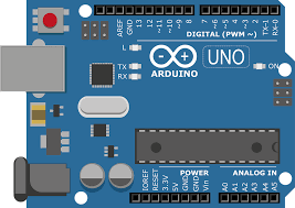
Arduino Uno ATmega328
Features of the Arduino Uno Board
The main features of the Arduino Uno (ATmega328) include the following:
- Operating voltage: 5 V
- Recommended input voltage: 7 V to 12 V
- Input voltage range: 6 V to 20 V
- Digital input/output pins: 14
- Analog input pins: 6
- DC current per I/O pin: 40 mA
- DC current from the 3.3 V pin: 50 mA
- Flash memory: 32 KB
- SRAM: 2 KB
- EEPROM: 1 KB
- Clock speed: 16 MHz
Arduino Uno Pin Diagram
The Arduino Uno board consists of several key sections, including power pins, analog pins, the ATmega328 microcontroller, an ICSP header, a reset button, a power LED, digital I/O pins, the onboard LED connected to pin 13, TX/RX pins for serial communication, a USB interface, and an external power supply connector.
A detailed description of the Arduino Uno board layout is explained below.
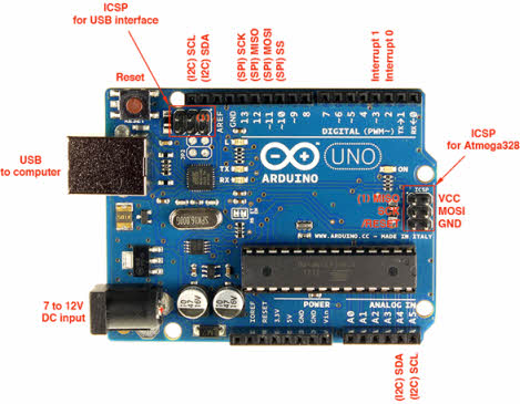
Arduino Uno board layout
Power Supply
The Arduino Uno can be powered either through a USB cable or an external power source. External power options include an AC-to-DC adapter or a battery. The adapter connects via the board’s power jack, while a battery can be connected through the Vin and GND pins on the power header. The recommended input voltage range is between 7 V and 12 V.
Input and Output
The Arduino Uno has 14 digital I/O pins, which can be configured as inputs or outputs using functions such as pinMode(), digitalWrite(), and digitalRead().
- Pin 0 (RX) and Pin 1 (TX) – Serial Communication: These pins are used to receive and transmit TTL serial data and are connected to the ATmega8U2 USB-to-serial interface.
- Pin 2 and Pin 3 – External Interrupts: These pins can trigger interrupts based on a low level or a change in signal value.
- Pins 3, 5, 6, 9, 10, and 11 – PWM: These pins provide 8-bit PWM output using the analogWrite() function.
- SPI Pins – Pin 10 (SS), Pin 11 (MOSI), Pin 12 (MISO), Pin 13 (SCK): These pins support SPI communication. Although SPI is handled by the hardware, it is not fully integrated into the core Arduino language.
- Pin 13 – Onboard LED: An LED is built into the board and connected to digital pin 13. The LED turns on when the pin is set HIGH and turns off when it is LOW.
- Pin 4 (SDA) and Pin 5 (SCL) – I2C: These pins support TWI (I2C) communication using the Wire library.
- AREF (Analog Reference): This pin provides a reference voltage for analog inputs when using the analogReference() function.
- Reset Pin: Used to reset the microcontroller.
Memory
The ATmega328 microcontroller on the Arduino Uno includes:
- 32 KB of flash memory for program storage
- 2 KB of SRAM
- 1 KB of EEPROM
Communication
The Arduino Uno ATmega328 supports UART TTL serial communication, available on digital pins TX (1) and RX (0). The Arduino IDE includes a Serial Monitor, making it easy to send and receive data. The board also has TX and RX LEDs that blink whenever data is transmitted or received via USB.
In addition, the SoftwareSerial library allows serial communication on other digital pins. The ATmega328P also supports I2C (TWI) and SPI communication, with built-in Arduino libraries simplifying the use of the I2C bus.
How to Use an Arduino Uno
The Arduino Uno can sense its environment through various inputs, such as sensors, and respond by controlling outputs like motors, LEDs, and other actuators. The ATmega328 microcontroller on the board is programmed using the Arduino programming language through the Arduino IDE (Integrated Development Environment). Arduino projects can also communicate with software running on a PC while the program is executing.
Arduino Programming
After installing the Arduino IDE on your computer, connect the Arduino Uno to the PC using a USB cable. Open the IDE and select the correct board by going to Tools → Board → Arduino Uno, then choose the correct port under Tools → Port. The board is programmed using the Arduino language, which is based on the Wiring framework.
To test the board and blink the onboard LED, load the example sketch by selecting File → Examples → Basics → Blink. Once the code is loaded into the IDE, click the Upload button on the toolbar. After the upload process finishes, you should see the LED on the board start blinking.
USB High-Voltage Protection
The Arduino Uno includes a resettable polyfuse that protects your computer’s USB port from overcurrent. Although most computers already have built-in protection, this fuse adds an extra layer of safety. If the current drawn from the USB port exceeds 500 mA, the fuse automatically disconnects the board until the excess current is removed.
Physical Characteristics
The Arduino Uno board measures approximately 2.7 × 2.1 inches. However, the USB connector and power jack slightly extend beyond these dimensions. The board also includes mounting holes, allowing it to be securely fixed to a surface or enclosure using screws.
Applications of Arduino Uno (ATmega328)
Common applications of the Arduino Uno include:
- Prototyping DIY and hobby projects
- Developing projects based on code-driven control
- Building automation systems
- Designing and testing basic electronic circuits
In summary, the Arduino Uno is based on an 8-bit ATmega328P microcontroller and includes essential components such as serial communication, a crystal oscillator, and a voltage regulator. The board features a USB interface, 14 digital I/O pins, 6 analog input pins, a barrel power jack, a reset button, and an ICSP header, making it a versatile platform for learning and development.
Related Articles
Diode Dynamics: Real-World Behavior in Fast Power and RF Circuits

Christopher Anderson
Christopher Anderson has a Ph.D. in electrical engineering, focusing on power electronics. He’s been a Senior member of the IEEE Power Electronics Society since 2021. Right now, he works with the KPR Institute of Engineering and Technology in the U.S. He also writes detailed, top-notch articles about power electronics for business-to-business electronics platforms.
Subscribe to JMBom Electronics !


