


Iron Core Inductor : Construction, Formula, Working & Its Applications
Catalog
What Is an Iron Core Inductor?Iron Core Inductor ConstructionTraditional Iron Core Inductor DesignWorking Principle of an Iron Core InductorIron Core Inductor vs. Air Core InductorIron Core Inductor FormulaHow to Choose an Iron Core InductorKey Factors That Affect InductanceAdvantages and Disadvantages of Iron Core InductorsApplications of Iron Core InductorsIn ConclusionFrequently Asked Questions about Iron Core and Ferrite Core InductorsRelated ArticlesInductors are used for the conversion of electrical energy in almost each power electronics circuit. These are active energy storage devices, used to provide stored energy in between different operating modes within a circuit. In addition, they can also work as filters, especially for switched current waveforms & also provides transient current limiting within snubber switches. Inductors are classified into different types depending on the specific materials & construction methods where every type of inductor has some benefits. So this article discusses one of the types of inductors like iron core inductor – working with applications.
What Is an Iron Core Inductor?
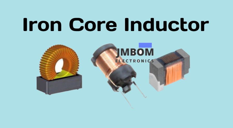
An iron core inductor is a type of fixed-value inductor that uses an iron core inside its coil to significantly boost its inductance. Although these inductors typically offer relatively low inductance compared to other core materials, the magnetic properties of the iron core greatly enhance the magnetic field strength. This makes them suitable for specific applications where a stronger magnetic field is beneficial. The standard symbol for an iron core inductor is shown below.
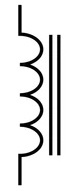
symbol for an iron core inductor
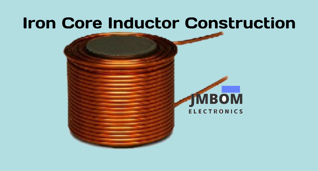
Iron Core Inductor Construction
An iron core inductor is built by winding a conductive material—typically insulated copper wire—around an iron core. The presence of the iron core enhances the inductor’s ability to store magnetic energy by intensifying the magnetic field. Compared to an air core inductor with the same number of turns, the iron core provides significantly better magnetic performance, making it more efficient at energy storage.
Traditional Iron Core Inductor Design
In a conventional iron core inductor design, a coil is helically wound around a core with a defined geometric shape, typically to optimize magnetic field concentration. The wire used for winding is often made from materials such as nickel, nickel-iron alloys, magnesium, or cadmium. Wire diameters typically range from 0.014 mm to 0.56 mm, depending on the current handling requirements and the frequency range of the application.
The number of coil turns (interwinding) directly affects the inductance generated, as it determines the level of electromagnetic induction when voltage is applied across the windings.
Traditional magnetic core inductors often use an iron or ferrite core wrapped within a magnetic circuit to achieve the desired inductance. A typical design includes two or more parallel cylindrical sections wound—often around a mandrel—and encapsulated with epoxy resin to form a magnetic barrier within the cylindrical structure. These longitudinal windings are usually configured into a closed-loop arrangement that corresponds to the effective magnetic path length of the core material, often expressed in terms of π (pi) geometry.
Working Principle of an Iron Core Inductor
The operating principle of an iron core inductor is based on the concept that magnetic induction is directly proportional to the rate of change of magnetic flux in a circuit. When an alternating current (AC) flows through the coil wound around an iron core, it generates a changing magnetic field. This varying field induces eddy currents within the iron core due to its conductive nature.
These eddy currents produce their own magnetic fields that oppose the original magnetic field—an effect described by Lenz’s Law. This opposition helps reduce unwanted voltage leakage and improves magnetic efficiency. The strength of this effect increases with the number of coil turns and the core’s material properties, including its resistance and permeability.
Because of this self-regulating magnetic behavior, iron core inductors can safely handle high electrical power levels without damage, making them ideal for applications that require strong and stable magnetic coupling.
Inductance Adjustment and Magnetic Energy Storage
Another important feature of iron core inductors is their adjustable inductance. Moving the iron core in or out of the coil alters the magnetic permeability of the inductor, thereby changing its inductance value. Compared to air core inductors, iron core inductors are significantly better at storing magnetic energy due to the high magnetic permeability of iron, which amplifies the magnetic field within the coil.
Iron Core Inductor vs. Air Core Inductor
The table below highlights the key differences between iron core and air core inductors:
| Feature | Iron Core Inductor | Air Core Inductor |
|---|---|---|
| Core Material | Uses a magnetic core made of iron or ferrite | Uses non-magnetic materials like ceramic, plastic, or just air |
| Inductance Value | Provides high inductance | Offers relatively low inductance |
| Magnetic Energy Storage | Excellent at storing magnetic energy | Less efficient in magnetic energy storage |
| Core Loss | Subject to core losses (e.g., eddy currents, hysteresis) | No core losses; ideal for high-frequency applications |
| Size | Generally larger in size | More compact and lightweight |
| Frequency Range | Suitable for applications up to several hundred MHz | Operates efficiently at frequencies up to 1 GHz |
| Typical Applications | Used in low-frequency systems: audio equipment, power supplies, inverters, etc. | Used in high-frequency systems: radio, TV receivers, RF circuits, etc. |
Iron Core Inductor Formula
The inductance of an inductor can be significantly affected by the material of the core. When a magnetic material such as iron or ferrite is used as the core, it increases the inductance due to its high magnetic permeability. On the other hand, using a non-magnetic material like copper or plastic reduces the inductance, as these materials do not effectively support magnetic field concentration.
The basic formula to calculate the inductance (L) of a coil is:L=N2⋅μ⋅AlL = \frac{{N^2 \cdot \mu \cdot A}}{l}L=lN2⋅μ⋅A
Where:
- L = Inductance in henries (H)
- N = Number of turns in the coil
- μ = Permeability of the core material (μ = μ₀ × μᵣ)
- A = Cross-sectional area of the core (in square meters)
- l = Length of the coil (in meters)
Note:
- μ₀ is the permeability of free space (approximately 4π×10−74\pi \times 10^{-7}4π×10−7 H/m)
- μᵣ is the relative permeability of the core material
How to Choose an Iron Core Inductor
Inductors vary in performance and characteristics depending on their shape, core material, and intended use. To select the right iron core inductor for your specific application, it's essential to understand these properties and how they align with your circuit’s requirements.
Several factors must be considered when choosing an iron core inductor, including:
- Inductor performance characteristics
- Circuit requirements
- Operating frequency (RF considerations)
- Physical size and shielding needs
- Tolerance levels
- Thermal and magnetic properties of the core material
A good understanding of the factors that influence inductance will help you make an informed decision.
Key Factors That Affect Inductance
The inductance of an iron core inductor depends on several physical and material-related parameters:
1. Number of Turns in the Coil
The inductance increases with the square of the number of turns. More turns result in a stronger magnetic field and higher inductance.
2. Length of the Coil
Inductance is inversely proportional to the length of the coil. A longer coil reduces the magnetic field density, leading to lower inductance.
3. Core Material
The permeability of the core material has a significant impact. Materials with higher magnetic permeability (like iron or ferrite) result in higher inductance by concentrating the magnetic field more effectively.
Advantages and Disadvantages of Iron Core Inductors
Advantages
- Low Core Losses: Iron core inductors typically have lower losses at low to medium frequencies.
- Simple Construction: They are relatively easy to design and manufacture.
- High Q-Factor: These inductors exhibit a high quality factor, meaning better energy efficiency in certain applications.
- High Inductance: Iron cores allow for a higher inductance value in a compact form, compared to air core inductors.
Disadvantages
- Increased Losses at High Frequencies: At higher frequencies, core losses (like eddy current and hysteresis losses) rise significantly.
- Complex Insulation Requirements: Due to the conductive nature of the core, more careful insulation is needed to prevent short circuits or performance degradation.
- Eddy Currents and Harmonics: These inductors are prone to eddy current generation and can introduce harmonic distortion in AC circuits.
Applications of Iron Core Inductors
Iron core inductors are commonly used in low to moderate frequency applications where high inductance is required. Typical uses include:
- Power Supply Filters: To smooth out ripple voltage and improve power stability.
- Audio Frequency (AF) Circuits: Widely used in AF applications such as audio amplifiers.
- Fluorescent Lighting: Serve as AF chokes to regulate current in fluorescent tube lights.
- Inverter Systems: Used in industrial and residential inverter applications.
- Industrial Power Supplies: Common in heavy-duty power equipment and power conditioning systems.
- Rapid Transit Systems: Used in power electronics for trains and other electric transit solutions.
In Conclusion
In conclusion, this article has provided an overview of iron core inductors, including their working principles, construction, advantages, and common applications. Most inductors feature a magnetic core—typically made of iron or ferrite—embedded within the coil. The presence of an iron core enhances the magnetic field strength, thereby significantly increasing the inductance value. As a result, iron core inductors can efficiently handle higher power levels, though they are generally not suitable for high-frequency applications due to core losses. Their typical use cases include low-frequency systems such as audio devices, industrial power supplies, and inverter circuits.
Frequently Asked Questions about Iron Core and Ferrite Core Inductors
1. What is an iron core inductor?
An iron core inductor is a type of inductor that uses a magnetic core—usually made of iron or ferrite—with a wire coil wound around it. These inductors are commonly used in power electronics, transformers, and circuits requiring energy storage or filtering. The magnetic core enhances the inductance and allows for better energy handling at lower frequencies.
2. What is the difference between iron core and air core inductors?
Iron core inductors have a magnetic core that significantly amplifies the magnetic field, enabling higher inductance and energy storage. In contrast, air core inductors use non-magnetic materials (like plastic or air) and have lower inductance for the same number of turns. While iron core inductors are ideal for low-frequency applications, air core inductors are better suited for high-frequency systems due to minimal core losses.
3. What does a ferrite core inductor do?
A ferrite core inductor uses a ferrimagnetic material as its core to guide and strengthen the magnetic field generated by current flowing through the coil. When the magnetic field changes, it induces an opposing current according to Faraday’s Law. These inductors convert electrical energy into magnetic energy and temporarily store it, making them effective for filtering, noise suppression, and switching power supplies.
4. What is a core inductor?
A core inductor is any inductor that includes a central core material to enhance its inductance. The core can be:
- Air (non-magnetic): Air-core inductors, for high-frequency applications.
- Magnetic material (iron or ferrite): Iron core inductors, for high inductance at lower frequencies.
The core type directly affects the inductor’s magnetic field strength and performance characteristics.
5. What is the purpose of an iron core?
The main function of an iron core is to strengthen the magnetic field generated by the current in the coil. A stronger magnetic field leads to greater inductance and better coupling in devices like transformers. In transformer applications, a changing magnetic field in the iron core induces a voltage in the secondary coil, generating alternating current (AC) in the connected circuit.
6. What are the disadvantages of ferrite core inductors?
Ferrite core inductors can suffer from core losses, which include:
- Eddy Current Losses: Increase exponentially with frequency.
- Hysteresis Losses: Increase linearly with changes in magnetic flux and frequency.
These losses make ferrite inductors less efficient at very high power levels or when exposed to rapidly changing magnetic fields.
Related Articles
Diode-Transistor Logic (DTL): Circuit Design,Truth Table, and Applications
2N5089 NPN Transistor: Overview, Pinout, and Common Uses
ESP32-S2 Development Board: Pinout, Features & Specs
ADXL335 Accelerometer Module: Pin Configuration, Features & Internal Components
Preamplifiers: What They Are, How They Work, Types and Differences
Metal Oxide Film Resistors: Structure, Operation and Key Specs
Semiconductor Fuse: Structure, HSN Code, Operation, and Common Uses
DC Servo Motor: Structure, Operation, Arduino Interface & Common Uses

Amanda Miller
Amanda Miller is a senior electronics engineer with 6 years of experience. She focuses on studying resistors, transistors, and package design in detail. Her deep knowledge helps her bring innovation and high standards to the electronics industry.
Subscribe to JMBom Electronics !


