


DC Servo Motor: Structure, Operation, Arduino Interface & Common Uses
Catalog
What is a DC Servo Motor?DC Servo Motor: Construction and Working PrincipleTransfer Function of a DC Servo MotorArmature-Controlled vs Field-Controlled DC Servo MotorsAC Servo Motor vs. DC Servo MotorArduino Code for Controlling DC Servo Motor with IR RemoteAdvantages and DisadvantagesApplications of DC Servo MotorsFrequently Asked Questions About DC Servo MotorsRelated ArticlesA servo motor—often just called a servo—is a type of electric motor designed to rotate machine components with high accuracy. It features a built-in control circuit that constantly monitors the position of the motor’s shaft. This feedback mechanism enables the motor to maintain precise rotational control. Servo motors are ideal for applications that require rotating an object to a specific position or angle.
There are two main types of servo motors: AC and DC. When powered by direct current (DC), the motor is known as a DC servo motor. If powered by alternating current (AC), it’s called an AC servo motor.
This guide focuses on DC servo motors—explaining how they work, how to interface them with an Arduino, and where they’re commonly used.
What is a DC Servo Motor?
A DC servo motor is a type of servo motor that operates using direct current (DC) to deliver precise mechanical output, such as position, speed, or acceleration. These motors are commonly used in systems that require quick and accurate movements—such as CNC machines, robotics, and computer-controlled equipment—where fast starts and stops are essential.
DC Servo Motor: Construction and Working Principle
A DC servo motor is made up of several key components, as shown in the block diagram below. Each part plays a specific role in the operation of the motor. The following sections explain the function of each component and how they work together to achieve precise motion control.
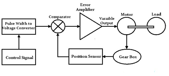
DC Servo Motor Block Diagram
The core of a DC servo motor system is a standard DC motor, where the field winding is separately excited. Based on how the excitation is applied, DC servo motors can be further classified into two types: armature-controlled and field-controlled.
The motor drives a mechanical load—typically something simple like a fan or an industrial component—directly connected to the motor’s shaft.
A gearbox is also included in the system, functioning as a mechanical transducer. It modifies the motor’s output—such as speed, position, or torque—to suit the specific needs of the application.
The position sensor plays a key role in feedback control. Its main function is to detect the current position of the load and generate a corresponding signal. In most cases, a potentiometer is used to convert the shaft’s angular position—via the gear mechanism—into a proportional voltage signal.
The comparator compares the position sensor’s output with a reference input to determine the difference, known as the error signal. This error signal is then sent to the amplifier. When the motor is operating with perfect accuracy, the error is zero. Together, the position sensor, gearbox, and comparator form a closed-loop control system.
The amplifier boosts the error signal from the comparator and sends it to the DC motor. This allows the system to act as a proportional controller, where the amplifier gain is tuned to reduce the steady-state error to zero for accurate motor positioning.
The control signal is fed into a pulse width modulator (PWM), which adjusts the motor’s input based on the feedback signal to ensure accurate operation with minimal steady-state error. The PWM works by comparing a reference waveform with the feedback signal to generate a series of pulses that control the motor.
In a closed-loop system, this setup allows precise control over the motor’s acceleration, speed, or position. As the name implies, a servo motor is a controlled motor that delivers the desired output by using both feedback and a controller. The system amplifies the error signal and uses it to adjust the motor’s behavior accordingly.
Advanced control techniques—such as those using FPGA chips or digital signal processors (DSPs)—further enhance the accuracy and responsiveness of these motors by improving how the control signals and PWM are generated.
How it works:
When a control signal is applied to the DC motor, it causes the motor shaft—and the connected gears—to rotate. The gear movement is fed back to the position sensor (usually a potentiometer), which also rotates. This rotation changes the sensor's resistance, which in turn alters its output voltage. This change is detected as an error signal, which is then sent to the controller. The controller processes this signal and generates a corresponding PWM signal to adjust the motor’s input, ensuring that the output matches the desired position.
Transfer Function of a DC Servo Motor
The transfer function of a system is defined as the ratio of the Laplace Transform (LT) of the output variable to the Laplace Transform of the input variable. In the case of a DC servo motor, the motor converts electrical energy into mechanical energy. Specifically, the electrical power supplied to the armature terminals is transformed into controlled mechanical motion.
Below is the transfer function for an armature-controlled DC servo motor, which represents the dynamic relationship between the motor’s input voltage and its resulting angular displacement or speed.
The transfer function of a DC servo motor describes the relationship between the input voltage and the output position in the Laplace domain.
1. Armature-Controlled DC Servo Motor
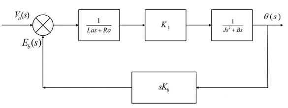
Armature Controlled DC Servo Motor Block Diagram
The transfer function is given by:θ(s)Va(s)=K1(Js2+Bs)(Las+Ra)1+K1KbKs(Js2+Bs)(Las+Ra)\frac{\theta(s)}{V_a(s)} = \frac{\frac{K_1}{(Js^2 + Bs)(L_a s + R_a)}}{1 + \frac{K_1 K_b K_s}{(Js^2 + Bs)(L_a s + R_a)}}Va(s)θ(s)=1+(Js2+Bs)(Las+Ra)K1KbKs(Js2+Bs)(Las+Ra)K1
Where:
- θ(s)\theta(s)θ(s) = output position in Laplace domain
- Va(s)V_a(s)Va(s) = input armature voltage
- JJJ = moment of inertia
- BBB = damping coefficient
- LaL_aLa, RaR_aRa = armature inductance and resistance
- K1K_1K1, KbK_bKb, KsK_sKs = motor constants
2. Field-Controlled DC Servo Motor
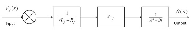
Field Controlled DC Servo Motor Block Diagram
The transfer function is:θ(s)Vf(s)=Kf(sLf+Rf)(Js2+Bs)\frac{\theta(s)}{V_f(s)} = \frac{K_f}{(sL_f + R_f)(Js^2 + Bs)}Vf(s)θ(s)=(sLf+Rf)(Js2+Bs)Kf
Where:
- Vf(s)V_f(s)Vf(s) = input field voltage
- LfL_fLf, RfR_fRf = field inductance and resistance
- KfK_fKf = field constant
Armature-Controlled vs Field-Controlled DC Servo Motors
- Armature-controlled DC servo motors offer better performance due to the closed-loop feedback system, resulting in more accurate and responsive control.
- In contrast, field-controlled servo motors operate in an open-loop configuration, leading to slower response times.
- The armature’s inductance is often considered negligible in armature-controlled designs, simplifying control and improving speed.
- In field-controlled systems, inductance cannot be ignored, which impacts dynamic performance.
- Additionally, damping enhancement—important for stability—is achievable in armature-controlled systems, but not possible in field-controlled configurations.
DC Servo Motor Specifications
DC servo motors are defined by a range of performance specifications. Selecting the right motor involves matching these specifications to the load requirements of your application to ensure proper performance and reliability.
- Shaft Speed: Indicates how fast the motor shaft rotates, typically measured in RPM (revolutions per minute). Manufacturers usually specify the no-load speed, which is the speed when the motor delivers zero output torque.
- Terminal Voltage: This is the rated voltage at which the motor is designed to operate. The motor’s speed can be controlled by adjusting the supplied voltage.
- Torque: The rotational force generated by the motor shaft. Required torque depends on the speed-torque characteristics of the application load. Torque is generally categorized as: Starting Torque: The torque needed to start the motor from a standstill. It is typically higher than the continuous torque. Continuous Torque: The torque the motor can deliver consistently during continuous operation without overheating.
To ensure reliable performance, the motor should have a torque and speed margin of 20–30% above the actual load requirements. However, significantly exceeding this margin can lead to unnecessary costs and reduced system efficiency.
Example: Faulhaber 12V Coreless DC Servo Motor Specifications
- Gearbox Ratio: 64:1 (Three-stage planetary gearbox)
- Load Current: 1400 mA
- Power Output: 17 W
- Rated Speed: 120 RPM
- No-load Current: 75 mA
- Encoder Type: Optical
- Encoder Resolution: 768 CPR (counts per revolution) at output shaft
- Motor Diameter: 30 mm
- Motor Body Length: 42 mm
- Total Length (including shaft and gearbox): 85 mm
- Shaft Diameter: 6 mm
- Shaft Length: 35 mm
- Stall Torque: 52 kg·cm
Characteristics of a DC Servo Motor
The key characteristics of a DC servo motor are:
- Its design is similar to that of a permanent magnet or separately excited DC motor.
- Speed control is achieved by varying the armature voltage.
- It is built with high armature resistance to enhance control characteristics.
- Offers a fast torque response, making it ideal for dynamic systems.
- A sudden change in armature voltage results in a quick change in motor speed, enabling precise and responsive control.
AC Servo Motor vs. DC Servo Motor
The table below highlights the key differences between AC and DC servo motors:
| Feature | AC Servo Motor | DC Servo Motor |
|---|---|---|
| Power Input | Uses AC electrical input | Uses DC electrical input |
| Output Power | Generally lower | Typically higher |
| Speed Range | Suited for high-speed operations | Suited for low-speed operations |
| Torque Output | Produces higher torque | Produces lower torque |
| Operation | Smooth, stable, and quiet | Less smooth and more noisy |
| Efficiency | Lower | Higher |
| Stability | More stable | Less stable, may require tuning |
| Electronic Noise | No electronic noise (brushless) | May generate noise due to brushes |
| Maintenance | Low maintenance (no brushes) | Higher maintenance (brushes and commutator) |
| Size & Weight | Lightweight and compact | Heavier and bulkier |
| Applications | Best for low-power applications | Ideal for high-power applications |
Interfacing a DC Servo Motor with Arduino Uno
To control a DC servo motor precisely at a desired angle, you can use an Arduino board or any similar microcontroller. The Arduino generates a PWM (Pulse Width Modulation) signal from its analog output, which drives the servo motor to the exact position required. Additionally, you can adjust the servo’s angle using input devices like a potentiometer or push buttons connected to the Arduino.
Another convenient method to control the servo motor is via an IR remote control. This allows you to set the motor to specific angles or incrementally increase and decrease its position using the remote’s buttons.
In this guide, we will focus on controlling the servo motor’s angle with an IR remote through Arduino. You’ll learn how to move the servo to a fixed angle, as well as how to rotate it clockwise or counterclockwise in steps using the remote.
The diagram below illustrates the wiring connections between the Arduino, the DC servo motor, and the IR remote. The interfacing connections are described as follows:
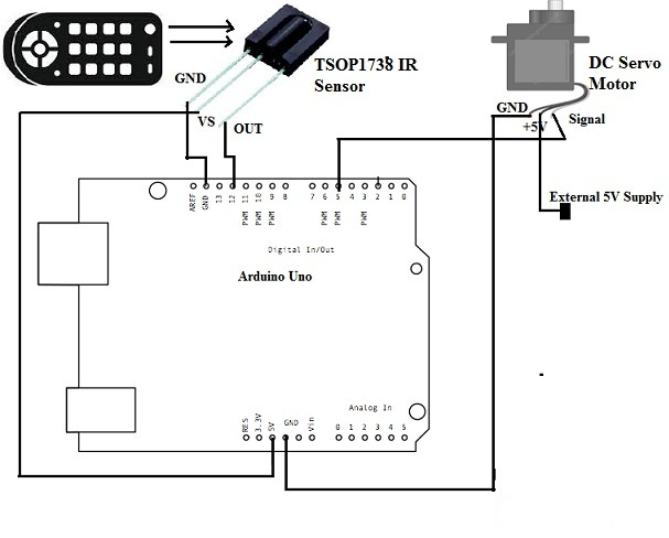
Interfacing DC Servo Motor with Arduino Uno
Interfacing Components and Connections
This setup primarily involves three key components: the DC servo motor, the Arduino Uno board, and the TSOP1738 IR sensor.
- The TSOP1738 IR sensor has three pins: Vcc, GND, and Output.
- Connect the sensor’s Vcc pin to the 5V output on the Arduino Uno.
- Connect the sensor’s GND pin to the Arduino’s GND.
- Connect the sensor’s Output pin to digital pin 12 on the Arduino (used as digital input).
The servo motor’s signal pin connects to digital pin 5 on the Arduino.
The servo’s positive power pin should be connected to an external 5V power supply, and its ground pin should be connected to the Arduino’s GND.
How It Works
The IR remote controls two main functions for the servo motor:
- Moving the motor to fixed angles (e.g., 30°, 60°, and 90°).
- Incrementally increasing or decreasing the motor’s angle within a 0° to 180° range.
The remote has various buttons—number keys (0-9), angle presets, arrow keys, and up/down controls.
- Pressing any digit button from 1 to 5 will move the servo motor to the corresponding preset angle.
- Pressing the angle up/down buttons adjusts the motor’s position in precise steps of ±5 degrees.
Each button press sends a unique IR code to the Arduino. To interpret these codes, you’ll use the IRremote library, which decodes the signals from the remote.
Next Steps
Upload the provided Arduino sketch to your board and connect the IR sensor. Point the remote towards the sensor and press any button. Open the Arduino Serial Monitor to view the decoded numeric code corresponding to the button pressed. This helps identify which button sends which code, so you can program the servo motor’s response accordingly.
Arduino Code for Controlling DC Servo Motor with IR Remote
cppCopyEdit#include <IRremote.h>  // Include IR remote library
#include <Servo.h>     // Include servo motor library

Servo servo1;          // Create servo object

int IRpin = 12;        // IR sensor input pin
int motor_angle = 0;   // Current servo angle

IRrecv irrecv(IRpin);  // Initialize IR receiver
decode_results results;

void setup() {
  Serial.begin(9600);                // Start serial communication
  Serial.println("IR Remote controlled servo motor");

  irrecv.enableIRIn();               // Start the IR receiver
  servo1.attach(5);                  // Attach servo to pin 5

  servo1.write(motor_angle);         // Initialize servo at 0 degrees
  Serial.println("Servo motor angle 0 deg");
  delay(2000);
}

void loop() {
  if (irrecv.decode(&results)) {    // When a button is pressed
    switch(results.value) {
      case 2210:   // Digit 1
        motor_angle = 30;
        Serial.println("Servo motor angle 30 deg");
        servo1.write(motor_angle);
        break;

      case 6308:   // Digit 2
        motor_angle = 60;
        Serial.println("Servo motor angle 60 deg");
        servo1.write(motor_angle);
        break;

      case 2215:   // Digit 3
        motor_angle = 90;
        Serial.println("Servo motor angle 90 deg");
        servo1.write(motor_angle);
        break;

      case 6312:   // Digit 4
        motor_angle = 120;
        Serial.println("Servo motor angle 120 deg");
        servo1.write(motor_angle);
        break;

      case 2219:   // Digit 5
        motor_angle = 150;
        Serial.println("Servo motor angle 150 deg");
        servo1.write(motor_angle);
        break;

      case 6338:   // Volume Up
        if (motor_angle < 150) motor_angle += 5;
        Serial.print("Motor angle is ");
        Serial.println(motor_angle);
        servo1.write(motor_angle);
        break;

      case 6292:   // Volume Down
        if (motor_angle > 0) motor_angle -= 5;
        Serial.print("Motor angle is ");
        Serial.println(motor_angle);
        servo1.write(motor_angle);
        break;

      default:
        Serial.println("Button not mapped");
        break;
    }
    delay(200);            // Short delay for button debounce
    irrecv.resume();       // Prepare to receive the next code
  }
}
How This Works
- Power the DC servo motor with an external 5V supply.
- Power the Arduino board and IR sensor via USB.
- On power-up, the servo motor moves to 0 degrees and the serial monitor displays: "Servo motor angle 0 deg".
- Press buttons 1 to 5 on the IR remote to move the servo to preset angles (30°, 60°, 90°, 120°, 150°). The new angle is shown on the serial monitor.
- Press the volume up button to increase the motor angle by 5°. For example, from 60° to 65°.
- Press the volume down button to decrease the motor angle by 5°. For example, from 90° to 85°.
The IR sensor detects the remote’s signals and sends them to the Arduino, which decodes the button presses and moves the servo accordingly. The updated angle is always printed on the serial monitor for easy tracking.
Advantages and Disadvantages
Advantages of DC Servo Motors
- Stable operation with reliable performance.
- High power output relative to their compact size and light weight.
- Operate quietly even at high speeds.
- Vibration- and resonance-free operation ensures smooth motion.
- High torque-to-inertia ratio, allowing rapid acceleration and quick load handling.
- High efficiency resulting in less energy waste.
- Provide fast response times for precise control.
- Portable and lightweight, making them ideal for various applications.
- Support four-quadrant operation (forward/reverse torque and speed control).
- Audibly quiet during high-speed operation.
Disadvantages of DC Servo Motors
- Inefficient cooling system, making them prone to overheating and contamination without proper ventilation.
- Peak output power occurs at high torque and speed, often requiring additional gearing.
- Susceptible to damage from overloads if protection isn’t implemented.
- Complex design that usually requires an encoder for accurate feedback.
- Require tuning and calibration to stabilize the feedback control loop.
- Need regular maintenance due to brushes and mechanical parts.
Applications of DC Servo Motors
DC servo motors find extensive use across various industries due to their precision and power. Common applications include:
- Machine tools for metal cutting and forming.
- Antenna positioning systems, as well as printing, packaging, woodworking, and textile machinery.
- Manufacturing of twine or rope, Coordinate Measuring Machines (CMM), and material handling equipment.
- Devices for floor polishing, automatic door openers, and X-Y positioning tables.
- Medical equipment and wafer spinning machines in semiconductor manufacturing.
- Aircraft control systems, where high power density is critical due to strict space and weight limitations.
- Applications requiring high starting torque, such as blower drives and fans.
- Widely used in robotics, programmable devices, electromechanical actuators, process controllers, and various automation systems.
This overview highlights how DC servo motors enable precise and efficient mechanical motion in diverse industrial and technological fields. Their performance characteristics make them a reliable choice for complex control tasks.
Frequently Asked Questions About DC Servo Motors
What is a DC servo motor?
DC servo motors are designed for precise control of angular position, velocity, and acceleration. They typically include separate field windings and armatures, a feedback device like a potentiometer or encoder, and operate within a closed-loop control system to ensure accurate motion.
What is the main advantage of using a DC servo motor?
The key advantage is their ability to achieve high acceleration rates, allowing rapid speed changes in very short intervals. This makes them ideal for industries such as packaging and printing, where speed and efficiency are critical.
Which is better, AC or DC servo motor?
AC servo motors generally offer several benefits over DC types, including higher torque-to-weight ratio, better efficiency, greater reliability, and lower radio frequency noise. They also require less maintenance and have longer lifespans since they lack a commutator.
Why use a servo motor instead of a regular motor?
Servo motors provide significantly higher torque density—about 40-60% more torque compared to similar-sized induction motors—making them more powerful and efficient for precision control.
When would you use a servo motor?
Servos are widely used in industrial applications like robotics, pharmaceuticals, food processing, and in-line manufacturing. They are also well-suited for electrically operated machinery such as elevators, rudders, walking robots, and robotic grippers.
What are the three types of servo motors?
Servo motors typically come in three varieties:
- Positional Rotation — rotate up to about 180 degrees, with built-in stops to prevent over-rotation.
- Continuous Rotation — can rotate full 360 degrees continuously, useful for robotic wheels or rotating arms.
- Linear — convert rotational motion into linear motion for applications requiring straight-line movement.
Can a servo motor turn 360 degrees?
Yes, some servo motors are designed for continuous rotation (360 degrees or more), enabling complex circular movements, such as those required in robotic arms or wheeled robots.
What is the alternative to a servo motor?
Stepper motors are a common alternative, especially for simple, open-loop motion control without feedback. They come in various sizes and are ideal when cost or size constraints exist. However, servo motors excel when low noise and vibration, as well as precise closed-loop control, are required.
Related Articles
Resistor-Transistor Logic (RTL):Operation, Features, and Applications
Diode-Transistor Logic (DTL): Circuit Design,Truth Table, and Applications
2N5089 NPN Transistor: Overview, Pinout, and Common Uses
ESP32-S2 Development Board: Pinout, Features & Specs
ADXL335 Accelerometer Module: Pin Configuration, Features & Internal Components
Preamplifiers: What They Are, How They Work, Types and Differences
Metal Oxide Film Resistors: Structure, Operation and Key Specs
Semiconductor Fuse: Structure, HSN Code, Operation, and Common Uses

Christopher Anderson
Christopher Anderson has a Ph.D. in electrical engineering, focusing on power electronics. He’s been a Senior member of the IEEE Power Electronics Society since 2021. Right now, he works with the KPR Institute of Engineering and Technology in the U.S. He also writes detailed, top-notch articles about power electronics for business-to-business electronics platforms.
Subscribe to JMBom Electronics !


