


Resistor-Transistor Logic (RTL):Operation, Features, and Applications
Catalog
What Is Resistor-Transistor Logic (RTL)?Resistor-Transistor Logic CircuitHow Does Resistor-Transistor Logic Operate?Key Characteristics of Resistor-Transistor Logic (RTL)Comparison: RTL vs DTL vs TTLAdvantages and Disadvantages of Resistor-Transistor Logic (RTL)Applications of Resistor-Transistor Logic (RTL)SummaryFrequently Ask QuestionsRelated ArticlesResistor-Transistor Logic (RTL) emerged in 1961, developed by Fairchild following the invention of integrated circuits (ICs). It laid the groundwork for the advancement of semiconductor technology. RTL was the first type of integrated circuit to incorporate both resistors and bipolar junction transistors, and it became the earliest digital logic family implemented as a monolithic IC. Although it was eventually replaced by Diode-Transistor Logic (DTL), RTL played a vital role in early digital design. Notably, RTL circuits were used in the Apollo Guidance Computer. This article offers a concise overview of RTL, including how it works, its key characteristics, and common applications.
What Is Resistor-Transistor Logic (RTL)?
Resistor-Transistor Logic (RTL) refers to the earliest type of integrated circuit made using resistors and bipolar junction transistors (BJTs). The term “RTL” comes from its operating principle—logic operations are carried out using resistor networks, while signal amplification is performed by transistors. A basic RTL setup typically includes a single input resistor and a transistor. In this configuration, the resistor limits the current and the transistor acts as a switching element. RTL logic implements basic digital functions such as inverters, where the output is the logical opposite of the input. RTL technology forms the foundation for designing digital circuits with logic gates that rely on a combination of resistors and transistors.
Resistor-Transistor Logic Circuit
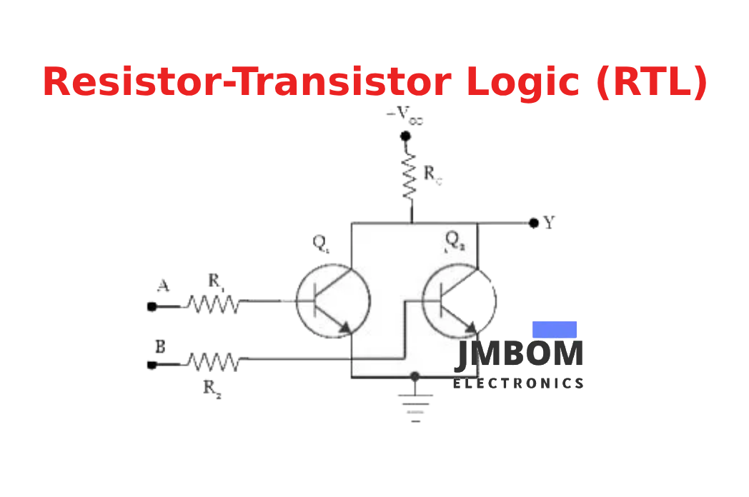
One of the simplest and most common digital logic circuits is the RTL circuit, which belongs to the bipolar saturated logic family. A typical example is the 2-input RTL NOR gate, constructed entirely from resistors and transistors. In this design, the input side features resistors (R1 and R2), while the output is formed using transistors (Q1 and Q2). This arrangement demonstrates how basic logic functions can be achieved through a combination of passive and active components in a compact circuit structure.
Inside the RTL Circuit
In this configuration, the emitter terminals of the transistors are directly connected to ground. The collector terminals of both transistors are tied together and linked to the positive supply voltage through a resistor labeled ‘RC’. This resistor, often referred to as a passive pull-up resistor, plays a crucial role in determining the output voltage when the transistors are off.
How Does Resistor-Transistor Logic Operate?
The operation of a 2-input RTL NOR gate is based on simple switching behavior. When both inputs—labeled A and B—are at a logic LOW level (0), there is not enough voltage to forward-bias the base-emitter junctions of the transistors. As a result, both transistors remain in the OFF state. With no conducting path to ground, the pull-up resistor RC allows the output node (Y) to rise to the supply voltage (+VCC), producing a logic HIGH (1) output.
If either input A or B (or both) is set to logic HIGH (1), the corresponding transistor becomes forward-biased and switches ON. This creates a conductive path from the collector through the transistor to ground. Current flows through RC and the conducting transistor, pulling the output voltage at node Y down to logic LOW (0).
Thus, the RTL NOR gate outputs a logic HIGH only when both inputs are LOW, fulfilling the NOR logic function.
When both inputs to the RTL circuit are at a HIGH logic level (1), both transistors turn ON simultaneously. This creates two parallel conduction paths from the supply voltage through each transistor to ground via the collector resistor (RC). As a result, the output at terminal ‘Y’ is pulled down to logic LOW (0).
This behavior confirms the NOR gate logic: the output is LOW when any input is HIGH, and only HIGH when all inputs are LOW. The corresponding truth table for the RTL NOR gate is shown below.
Key Characteristics of Resistor-Transistor Logic (RTL)
Here are the main electrical and performance characteristics of RTL:
- Fan-out: 5 (each output can drive up to five inputs)
- Propagation delay: Approximately 25 nanoseconds
- Power dissipation: Around 12 milliwatts per gate
- Noise margin (Low-level input): About 0.4 volts
- Noise immunity: Relatively low, making it susceptible to electrical noise
- Switching speed: Limited; slower compared to newer logic families
Comparison: RTL vs DTL vs TTL
The primary differences between Resistor-Transistor Logic (RTL), Diode-Transistor Logic (DTL), and Transistor-Transistor Logic (TTL) are summarized as follows:
RTL vs DTL vs TTL – Key Differences
| Logic Family | RTL (Resistor-Transistor Logic) | DTL (Diode-Transistor Logic) | TTL (Transistor-Transistor Logic) |
|---|---|---|---|
| Full Form | Resistor-Transistor Logic | Diode-Transistor Logic | Transistor-Transistor Logic |
| Components Used | Built using resistors and bipolar junction transistors (BJTs) | Uses diodes, resistors, and BJTs | Constructed with only BJTs and resistors |
| Design Complexity | Very simple design | Relatively simple design | More complex than RTL and DTL |
| Switching Speed | Slow response time | Faster than RTL | Significantly faster |
| Power Dissipation | High power loss | Lower power consumption | Very low power dissipation |
| Applications | Used in early computer systems | Suitable for basic switching and logic circuits | Common in modern ICs and high-speed digital systems |
| Operation | Basic and straightforward logic operations | Faster operation with better performance | Highly optimized for speed and efficiency |
Advantages and Disadvantages of Resistor-Transistor Logic (RTL)
Advantages of RTL
- Minimal use of transistors: RTL circuits require a small number of transistors to combine multiple input signals, which also allows them to amplify and invert the resulting output efficiently.
- Low-cost and simple design: RTL gates are straightforward in structure and inexpensive to manufacture, making them ideal for basic digital applications.
- Availability of both signal polarities: RTL circuits often provide both normal and inverted outputs, which can be useful in various logic designs.
- Ease of implementation: Their simple structure and low component count make RTL circuits easy to design and integrate into early digital systems.
- Foundation for modern logic families: While RTL is largely obsolete today, it laid the groundwork for more advanced logic families like TTL and CMOS, which offer better performance and efficiency.
- Reduced component usage: By minimizing the number of active elements, RTL circuits help reduce overall semiconductor usage in small-scale designs.
Disadvantages of RTL
- High current consumption: When the transistor is fully turned on, it can cause excessive current flow through the output biasing resistor, leading to increased power dissipation.
- Significant power loss: Power consumption remains high due to constant current flow through the base and collector resistors during switching.
- Limited fan-in capability: RTL gates can handle only a small number of input signals effectively, restricting their scalability.
- Slow switching speed: Compared to other logic families, RTL circuits operate relatively slowly because of their reliance on resistive-capacitive charging and discharging.
- Poor noise immunity: RTL circuits are more prone to electrical noise and signal degradation, which can affect their reliability.
- Higher voltage requirements: RTL often needs relatively high supply voltages for stable operation, limiting compatibility with lower-voltage systems.
- Design limitations: While individual gates are simple, complex RTL systems can become bulky and less efficient compared to modern logic technologies.
Applications of Resistor-Transistor Logic (RTL)
- Used in the Apollo Guidance Computer: RTL integrated circuits were famously used in NASA’s Apollo Guidance Computer, one of the earliest real-world applications of digital ICs in aerospace technology.
- Foundation of early digital logic systems: RTL served as the basic building block for early digital logic families, enabling the construction of simple logic gates and small-scale digital circuits.
Summary
Resistor-Transistor Logic (RTL) represents an early class of digital circuits built using resistors and bipolar junction transistors (BJTs). As one of the first logic families developed for integrated circuits, RTL played a vital role in the evolution of semiconductor technology. In these circuits, resistors are used primarily to limit current, while NPN transistors function as switches to perform logical operations.
Despite being largely replaced by more advanced logic families like TTL and CMOS, RTL remains historically significant for its simplicity and contribution to the development of early digital systems.
Question for You:
What is DTL (Diode-Transistor Logic), and how does it improve upon RTL?
Frequently Ask Questions
What is Resistor-Transistor Logic (RTL)?
Resistor–Transistor Logic (RTL), also known as Transistor–Resistor Logic (TRL), is a family of digital circuits that use resistors for input signal control and bipolar junction transistors (BJTs) for switching. It was one of the earliest forms of digital logic used in integrated circuits.
How Does RTL Work?
In its simplest form, an RTL circuit consists of a resistor connected to the input and a transistor acting as a switch. The resistor limits current, and the transistor responds to the input signal by turning ON or OFF, thereby performing basic logic functions such as inversion (NOT gate).
Why Is a Resistor Needed Before a Transistor?
A resistor is placed before the base of a transistor to limit the input current and stabilize the transistor's operation. Applying a voltage directly (e.g., from an IC output) without a resistor can cause the transistor to behave unpredictably or even get damaged due to excessive current.
How Does Transistor Logic Work?
Transistor logic, such as Transistor-Transistor Logic (TTL), uses BJTs as both input and output devices. Transistors in TTL circuits are driven into saturation, where they fully conduct, enabling fast switching. One transistor amplifies the input signal, while another performs the actual switching function.
What’s the Main Difference Between RTL and DTL?
- RTL (Resistor-Transistor Logic) uses resistors for input control and transistors for switching.
- DTL (Diode-Transistor Logic) uses diodes at the input stage and transistors at the output.
- TTL (Transistor-Transistor Logic) relies entirely on transistors.
DTL offers better speed and noise immunity compared to RTL.
Are Transistors the Same as Logic Gates?
Transistors themselves are not logic gates, but they are the building blocks of logic gates. By arranging transistors in specific configurations, they can perform logic functions like AND, OR, NOT, etc. Most modern logic gates are built using MOSFETs rather than BJTs.
What Is the Primary Advantage of RTL?
The biggest advantage of RTL is that it requires a minimal number of transistors, making it simple and cost-effective to design. However, this simplicity comes at the cost of high power dissipation and low noise immunity.
What Is RTL in Simple Terms?
The term RTL can also refer to Register Transfer Level in digital design. It describes a design abstraction where data flows between registers, and operations are defined by clock-driven transfers. It’s commonly used in hardware description languages (HDLs) like Verilog and VHDL.
Is RTL a Coding Language?
No, RTL itself is not a programming language. However, RTL coding refers to writing code (typically in Verilog or VHDL) that describes hardware behavior at the register-transfer level. RTL coding is used in digital synthesis tools to create real hardware circuits from high-level logic.
Related Articles
LF353N Op-Amp Explained: Pinout, Features, and How It Works
ADXL335 Accelerometer Sensor: Pinout, Specs, Features, and How It Works
Engine Coolant Temperature Sensor: Overview, Function & Circuit Design
Crankshaft Position Sensor: Overview, Circuit Function& Comparison with Camshaft Sensors
Inverting Summing Amplifier: Circuit Diagram,Operation and Formula
Active Bandpass Filter: Overview, Types,Q Factor & Applications
Passive High-Pass Filter: Overview, Circuit Design & Transfer Function
Differential Pressure Sensors: Working Principle, Interfacing,Testing Methods and Common Issues
Voltage Amplifier: Circuit Design, Gain, vs. Power Amplifier, and Key Applications

Christopher Anderson
Christopher Anderson has a Ph.D. in electrical engineering, focusing on power electronics. He’s been a Senior member of the IEEE Power Electronics Society since 2021. Right now, he works with the KPR Institute of Engineering and Technology in the U.S. He also writes detailed, top-notch articles about power electronics for business-to-business electronics platforms.
Subscribe to JMBom Electronics !


