


Passive High-Pass Filter: Overview, Circuit Design & Transfer Function
Catalog
What Is a Passive High-Pass Filter?Passive High-Pass Filter CircuitTransfer Function of a Passive High-Pass FilterTypes of Passive High-Pass FiltersApplications of Passive High-Pass FiltersSummaryFrequently Ask QuestionsRelated ArticlesA passive high-pass filter (HPF) is an electronic circuit that allows signals above a certain cutoff frequency to pass through while attenuating those below it. It performs the opposite function of a low-pass filter and is often referred to as a bass-cut or low-cut filter. When combined with a low-pass filter, it forms a band-pass filter that permits only a specific frequency range to pass.
High-pass filters come in various forms depending on their circuit configuration and components. These include passive and active HPFs, RC-based HPFs, as well as first-order, second-order, Butterworth, Chebyshev, and Bessel high-pass designs. This article provides an in-depth look at passive high-pass filters, covering their circuit structure, working principle, types, transfer function, and practical uses.
What Is a Passive High-Pass Filter?
A passive high-pass filter is a type of electronic circuit that permits high-frequency signals to pass while attenuating lower-frequency signals. It's termed "passive" because it operates without any external power source, relying solely on the energy of the input signal.
This filter is built using passive components such as resistors, capacitors, and inductors. The values of these components determine the cutoff frequency—the point at which lower-frequency signals begin to be filtered out.
Passive High-Pass Filter Circuit
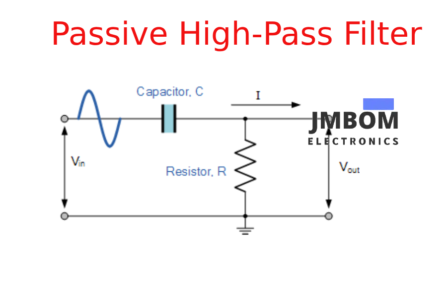
The basic circuit design of a passive high-pass filter consists of a resistor and a capacitor arranged in a specific configuration. While it shares similarities with a passive low-pass filter, the positions of the resistor and capacitor are simply reversed. In this setup, the capacitor is placed in series with the input signal, followed by a resistor connected to ground.
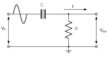
When an AC input signal is applied to the series connection of a non-polarized capacitor and a resistor, the filtered output is taken across the resistor. This configuration allows high-frequency signals to pass through while attenuating lower-frequency ones.
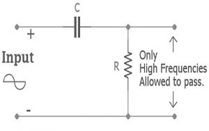
Passive High Pass Filter
The cutoff frequency of the filter is determined by the values of the resistor and capacitor used. This type of filter is commonly used in high-frequency applications, especially around the 10 MHz range. Due to the reversed component arrangement compared to a low-pass filter, the capacitor’s response behaves inversely, resulting in opposite frequency characteristics.
At low frequencies, the capacitor in a passive high-pass filter behaves like an open circuit, effectively blocking the signal. At higher frequencies, however, it begins to act more like a short circuit, allowing the signal to pass through. This behavior is due to the capacitor’s capacitive reactance (Xc)—which is inversely proportional to frequency.
At lower frequencies, the capacitive reactance is high, so the capacitor resists the flow of current and prevents the signal from reaching the output. As the input frequency increases, the capacitive reactance decreases, allowing more current to flow through the circuit. Once the signal frequency exceeds the cutoff frequency (fc), the capacitor offers minimal opposition, and the signal passes almost entirely to the output.
In this filter, frequencies below the cutoff point are significantly attenuated and fall within what is known as the stop band, while frequencies above the cutoff point are allowed to pass through, forming the pass band. This frequency-selective behavior is what makes the passive high-pass filter effective in applications where low-frequency signals need to be blocked.
Cutoff Frequency
The cutoff frequency (fcf_cfc) of a passive high-pass filter is calculated using the same formula as a low-pass filter:fc=12πRCf_c = \frac{1}{2 \pi R C}fc=2πRC1
where RRR is the resistance and CCC is the capacitance in the circuit.
Phase Angle of Passive High-Pass Filter
The phase shift of a passive high-pass filter is represented by the symbol ϕ\phiϕ (phi). At the cutoff frequency (where the output is down by 3 dB), the phase angle is typically around +45°. Unlike a low-pass filter, where the phase shift is negative, the high-pass filter produces a positive phase shift.
The phase shift at any frequency fff can be calculated as:ϕ=arctan(12πfRC)\phi = \arctan\left(\frac{1}{2 \pi f R C}\right)ϕ=arctan(2πfRC1)
The filter allows all signals with frequencies above the cutoff to pass through with this characteristic phase shift.
Time Constant
The time constant, denoted as τ\tauτ (tau), describes how quickly the capacitor charges and discharges in response to the input signal frequency. It relates directly to the cutoff frequency and is given by:τ=RC=12πfc\tau = R C = \frac{1}{2 \pi f_c}τ=RC=2πfc1
If the time constant τ\tauτ is known, the cutoff frequency can be found by rearranging the formula:fc=12πRC=12πτf_c = \frac{1}{2 \pi R C} = \frac{1}{2 \pi \tau}fc=2πRC1=2πτ1
Example Calculation
Consider a passive high-pass filter using a 330 kΩ resistor and a 100 pF capacitor. To find the cutoff frequency:fc=12πRCf_c = \frac{1}{2 \pi R C}fc=2πRC1
Substituting the values:fc=12×3.14×330,000×100×10−12≈4,825 Hz(4.825 kHz)f_c = \frac{1}{2 \times 3.14 \times 330,000 \times 100 \times 10^{-12}} \approx 4,825 \text{ Hz} \quad (4.825 \text{ kHz})fc=2×3.14×330,000×100×10−121≈4,825 Hz(4.825 kHz)
Transfer Function of a Passive High-Pass Filter
The transfer function describes the mathematical relationship between the input and output signals of a passive high-pass filter. It helps analyze how the filter responds to different frequencies. The derivation is as follows:
Passive HPF Transfer Function
Start with the input voltage across the series RC circuit:Vin=I⋅Z=I⋅(R+1jωC)V_{in} = I \cdot Z = I \cdot \left(R + \frac{1}{j\omega C}\right)Vin=I⋅Z=I⋅(R+jωC1)
The output voltage is taken across the resistor:Vo=I⋅RV_o = I \cdot RVo=I⋅R
Now, the transfer function H(ω)=VoVinH(\omega) = \frac{V_o}{V_{in}}H(ω)=VinVo becomes:VoVin=IRI(R+1jωC)=R⋅jωCR⋅jωC+1\frac{V_o}{V_{in}} = \frac{IR}{I\left(R + \frac{1}{j\omega C}\right)} = \frac{R \cdot j\omega C}{R \cdot j\omega C + 1}VinVo=I(R+jωC1)IR=R⋅jωC+1R⋅jωC
Let’s normalize it using:ωc=1RC\omega_c = \frac{1}{RC}ωc=RC1
Then the transfer function simplifies to:VoVin=j(ωωc)1+j(ωωc)\frac{V_o}{V_{in}} = \frac{j\left(\frac{\omega}{\omega_c}\right)}{1 + j\left(\frac{\omega}{\omega_c}\right)}VinVo=1+j(ωcω)j(ωcω)
This is the standard transfer function of a passive high-pass filter, which can be used to determine the voltage gain at any frequency ω\omegaω.
Types of Passive High-Pass Filters
Passive high-pass filters are typically categorized by their order, which indicates how sharply they can transition between blocking and passing frequencies. The main types are:
First-Order Passive High-Pass Filter
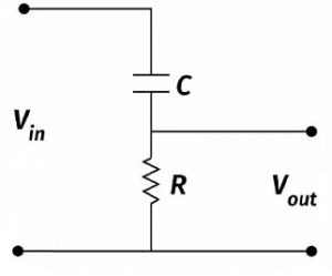
A first-order passive high-pass filter uses one resistor and one reactive component—usually a capacitor. It allows frequencies above a certain cutoff to pass while attenuating lower frequencies. The output is taken across the resistor in a series RC network.
This type of filter does not require any external power supply, as it relies solely on passive components.
First Order Passive High Pass Filter Circuit
The cutoff frequency for a first-order HPF is calculated using the familiar formula:fc=12πRCf_c = \frac{1}{2 \pi R C}fc=2πRC1
This equation is identical to that of a first-order low-pass filter, with the roles of the resistor and capacitor reversed.
Second-Order Passive High-Pass Filter
A second-order passive high-pass filter is created by cascading two first-order HPF stages. This circuit consists of two resistors and two capacitors, forming a two-stage RC network. Compared to a single-stage (first-order) filter, the second-order design provides a steeper roll-off, typically at a rate of –40 dB per decade, improving its ability to attenuate low-frequency signals.
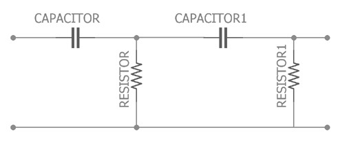
Second Order Passive High Pass Filter
The increased efficiency of this filter is due to the presence of two energy storage components, which enhances frequency selectivity. The cutoff frequency for a second-order passive HPF depends on the values of the resistors and capacitors used and is given by:fc=12πR1C1R2C2(Hz)f_c = \frac{1}{2\pi \sqrt{R_1 C_1 R_2 C_2}} \quad \text{(Hz)}fc=2πR1C1R2C21(Hz)
Applications of Passive High-Pass Filters
Passive high-pass filters have a wide range of applications, particularly in signal processing and audio systems. Some common uses include:
- Signal conditioning: Blocking low-frequency noise while allowing high-frequency signals to pass.
- Audio systems: Used in equalizers and audio receivers to remove bass hums and low-end noise.
- Music processing: Common in audio mixers and sound systems to control treble and high-frequency clarity.
- Waveform generators: Utilized in function generators, pulse generators, and ramp-to-step signal converters.
- Oscilloscopes and CRTs: Helps shape and refine signal edges.
- Image processing: Enhances high-frequency details and edges in digital image applications.
- Industrial and scientific instrumentation: Found in systems such as radar, seismic monitoring, and biomedical devices (e.g., ECG interpretation).
- General electronic systems: Essential in circuits where it is necessary to suppress low-frequency components and maintain high-frequency fidelity.
Summary
To conclude, a passive high-pass filter is a simple yet essential electronic circuit designed using only passive components—resistors and capacitors. These filters do not require any external power supply, and since they contain no active elements, they provide no gain. As a result, the output signal amplitude is always equal to or less than the input.
Their simplicity, low cost, and effectiveness make them ideal for a wide variety of filtering applications. Now, here's something to think about: What is a passive low-pass filter?
Frequently Ask Questions
What is a Passive High-Pass Filter?
A passive high-pass filter is a basic circuit made with a resistor and capacitor (RC). The input signal passes through the series RC network, and the output is taken across the resistor. At low frequencies, the capacitor blocks the signal, while at higher frequencies, it allows the signal to pass through to the resistor. This simple design doesn’t require any external power and is commonly used for filtering out low-frequency noise.
What Are the Four Types of Passive Filters?
Passive filters are built using only passive components such as resistors, capacitors, and inductors. The four primary types of passive filters include:
- Low-Pass Filter (LPF) – passes low frequencies, blocks high ones
- High-Pass Filter (HPF) – passes high frequencies, blocks low ones
- Band-Pass Filter (BPF) – passes a range of frequencies
- Band-Stop (Notch) Filter – blocks a specific frequency band
These filters are commonly used in applications like power supplies, audio electronics, and radio communication systems.
What Does a High-Pass Filter Do?
A high-pass filter (HPF) removes frequencies below a designated cutoff frequency, allowing higher frequencies to pass through. This is useful for eliminating low-end rumble or background noise, improving clarity in audio and signal processing.
Does a High-Pass Filter Remove Bass?
Yes. High-pass filters remove low-frequency content, which includes bass frequencies. This clears up the lower end of the audio mix, making more room for key elements like kick drums or bass lines, and reducing muddiness in the overall sound.
Should I Use a High-Pass Filter on Vocals?
Absolutely. Applying a high-pass filter to vocals is a common mixing technique. It helps vocals stand out by removing unnecessary low-frequency sounds (like mic handling noise or room rumble), ensuring clarity in a dense mix.
What Are the Disadvantages of Passive Filters?
While passive filters are simple and don’t require power, they have some limitations:
- Limited control over frequency response
- No amplification (gain ≤ 1)
- Can be bulky, especially when inductors are involved
- Less effective at sharp filtering compared to active filters
How to Tell If a Filter Is Active or Passive?
The difference lies in the components:
- Passive Filters: Use only resistors, capacitors, and inductors. No external power source is needed.
- Active Filters: Include operational amplifiers (op-amps) along with passive components. These require a power supply and can provide gain and better frequency control.
How Does a Passive High-Pass Filter Work?
A passive high-pass filter passes signals above its cutoff frequency while blocking or attenuating signals below that threshold. The capacitor’s reactance decreases as frequency increases, allowing higher-frequency signals to reach the output. This is the opposite behavior of a low-pass filter, which allows only low frequencies to pass.
Related Articles
ESP32-S3 Development Board: Pinout Diagram, Key Features, Technical Specs
DS18B20 Waterproof Temperature Sensor: Overview, Operation, and Common Uses
BAT54A Schottky Diode: Pinout and Common Uses
Infineon ILD8150E LED Driver IC Overview
LF353N Op-Amp Explained: Pinout, Features, and How It Works
ADXL335 Accelerometer Sensor: Pinout, Specs, Features, and How It Works
Engine Coolant Temperature Sensor: Overview, Function & Circuit Design
Crankshaft Position Sensor: Overview, Circuit Function& Comparison with Camshaft Sensors
Inverting Summing Amplifier: Circuit Diagram,Operation and Formula
Active Bandpass Filter: Overview, Types,Q Factor & Applications

Amanda Miller
Amanda Miller is a senior electronics engineer with 6 years of experience. She focuses on studying resistors, transistors, and package design in detail. Her deep knowledge helps her bring innovation and high standards to the electronics industry.
Subscribe to JMBom Electronics !


