


Active Bandpass Filter: Overview, Types,Q Factor & Applications
Catalog
What is an Active Bandpass Filter?How Does an Active Bandpass Filter Work?Active Bandpass Filter Circuit DesignFrequency Response and Phase CharacteristicsQ Factor (Quality Factor) of Active Bandpass FiltersTypes of Active Bandpass FiltersVoltage Gain ExpressionsNarrow Bandpass FilterAdvantages and Disadvantages of Active Bandpass FiltersApplications of Active Bandpass FiltersWhere Are Active Bandpass Filters Used?What Is the Difference Between Active and Passive Bandpass Filters?What Is the Transfer Function of a Bandpass Filter?What Is a Filter Transfer Function?SummaryFrequently Ask QuestionsRelated ArticlesA bandpass filter is a circuit that allows signals within a specific frequency range to pass through while blocking signals outside that range. These filters come in different forms. Some use active components like transistors and operational amplifiers, along with a power supply—these are known as active bandpass filters (BPFs). Others are made using only passive elements such as capacitors and inductors, and are called passive BPFs.
Bandpass filters are widely used in wireless communication systems. In transmitters, they help limit the signal bandwidth to the necessary range, ensuring efficient data transmission. In receivers, they allow only the desired frequency range to be processed while rejecting unwanted signals, helping to improve the signal-to-noise (S/N) ratio. This article gives an overview of active bandpass filters, including how they work, their types, frequency response, and practical applications.
What is an Active Bandpass Filter?
An active bandpass filter is a type of bandpass filter that uses active components—typically an operational amplifier (op-amp)—along with resistors and capacitors. Unlike passive filters, active BPFs can amplify signals in addition to filtering them. However, they require an external power source to function.
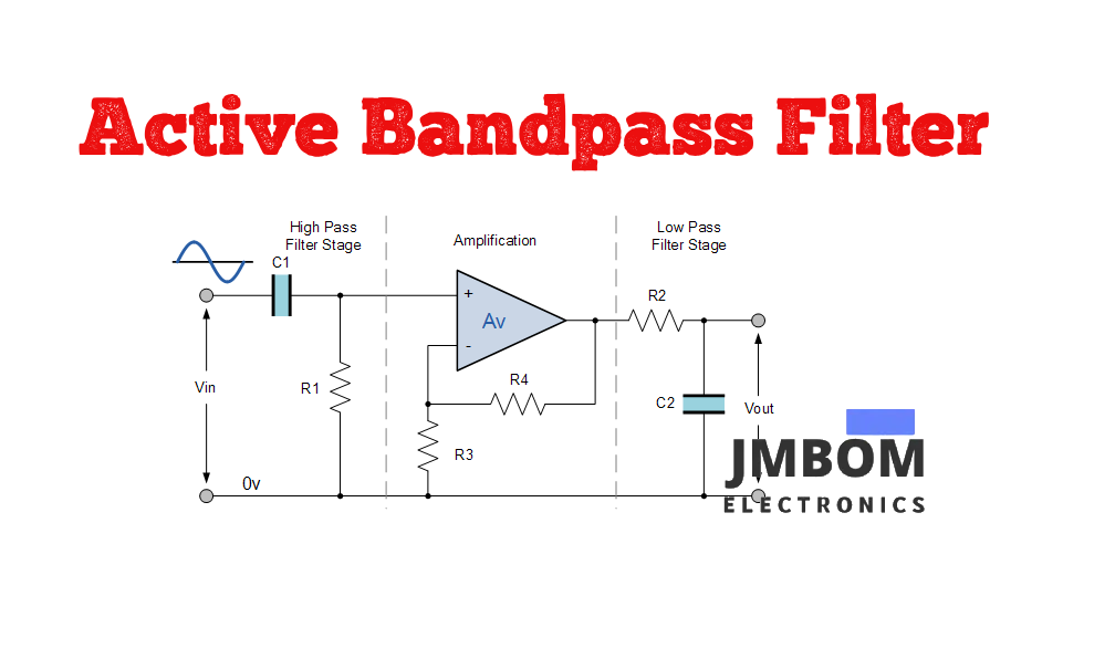
A basic active bandpass filter is constructed by combining a high-pass filter (HPF), an amplifier, and a low-pass filter (LPF) in sequence. The amplifier serves two purposes: it provides gain and isolates the HPF and LPF stages to prevent interaction between them. To ensure the filter operates correctly, the cutoff frequencies of both the HPF and LPF need to be closely matched. If they differ too much, it can affect the overall performance of the filter—hence the need for proper amplification and stage separation.
How Does an Active Bandpass Filter Work?
An active bandpass filter allows signals within a defined frequency range (called the passband) to pass through, while attenuating signals that fall outside this range—both lower and higher frequencies. The filter’s design ensures that signals in the desired frequency band are minimally affected, while unwanted frequencies are significantly reduced.
Active Bandpass Filter Circuit Design
Below is a typical circuit diagram of an active bandpass filter. The design combines separate low-pass and high-pass filter sections. The initial stage is a high-pass filter, which includes a capacitor to block any DC components from the input. This is followed by an amplifier, and then a low-pass filter.
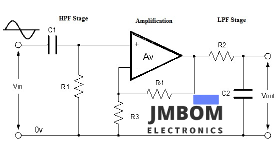
Active Bandpass Filter Circuit
This configuration results in a low-Q filter, meaning it has a wide bandwidth. If a more selective or narrow bandwidth is required, adjustments can be made to the component values or a higher-order filter design can be used.
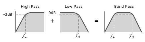
High Pass Response
Active Bandpass Filter – Frequency Response & Design Characteristics
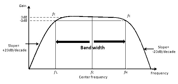
This type of filter design offers the advantage of producing a relatively flat yet asymmetrical passband response. One side of the passband reflects the characteristics of a low-pass filter, while the other mirrors a high-pass filter.
The upper cut-off frequency (ƒH) and lower cut-off frequency (ƒL) are determined in the same way as in standard first-order LPF and HPF circuits. To ensure stable performance and reduce interaction between the two stages, there should be a sufficient gap between ƒH and ƒL. The operational amplifier in the circuit provides isolation between the HPF and LPF sections and also contributes to the overall voltage gain of the bandpass filter. The bandwidth of the filter is simply the difference between the two -3dB cutoff points:
Bandwidth = ƒH - ƒL
Frequency Response and Phase Characteristics
When a passive-tuned filter is used as a bandpass filter, the resulting bandwidth tends to be relatively wide. This can be a disadvantage when narrow-band frequency selection is needed. However, active bandpass filters—especially those designed with inverting op-amps—allow for more precise control of the bandwidth and response characteristics.
By adjusting the positions of the resistors and capacitors in the filter configuration, a more refined and efficient frequency response can be achieved. In an active BPF, the lower -3dB cutoff frequency is labeled as ƒC1, and the upper -3dB cutoff frequency is labeled as ƒC2.
This filter design incorporates two main stages—HPF and LPF—with separate center frequencies. Importantly, the center frequency of the HPF should be lower than that of the LPF.
The center frequency (fr) of the bandpass filter is calculated as the geometric mean of the upper and lower cutoff frequencies:
fr = √(ƒH × ƒL)
Gain and Amplitude Response
The voltage gain of the active BPF is given by the formula:
Gain (dB) = 20 log (Vout / Vin)
The amplitude response of the overall filter depends on the individual responses of the LPF and HPF sections. The shape and sharpness of the response curve are influenced by the filter order—that is, how many stages are cascaded together.
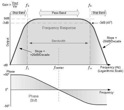
Active Bandpass Filter Frequency Response
Q Factor (Quality Factor) of Active Bandpass Filters
The Q factor, or quality factor, of an active bandpass filter is determined by the width of the passband—the frequency range between the upper and lower -3dB cutoff points. A lower Q value indicates a wider bandwidth, while a higher Q value corresponds to a narrower passband, resulting in a sharper frequency response.
In some contexts, the Q factor is represented by the Greek symbol α (alpha) and is referred to as the alpha-peak frequency, where:
α = 1 / Q
Since the Q factor defines how sharply the filter responds around its resonant or center frequency (ƒr), it’s also associated with the damping behavior of the filter. A high Q indicates less damping and a more selective (sharper) response, while a low Q indicates greater damping and a flatter response curve.
The damping ratio is often denoted by the Greek symbol ξ (xi) and is calculated as:
ξ = α / 2
The Q factor is mathematically expressed as the ratio between the center (resonant) frequency and the bandwidth (BW) of the filter:
Q = ƒr / BW
Types of Active Bandpass Filters
Active bandpass filters are generally classified into two categories:
1. Wide Bandpass Filter
When the Q value is below 10, the filter is said to have a wide passband, and the resulting bandwidth is relatively large. Such filters are referred to as wide bandpass filters. In this type, the upper cutoff frequency (ƒH) is significantly higher than the lower cutoff frequency (ƒL).
In a typical wide BPF, the signal first passes through a high-pass filter (HPF), which removes low-frequency content. The output from the HPF is then fed into a low-pass filter (LPF), which attenuates the high-frequency components. Together, these form a simple bandpass filter.
To ensure balanced performance, the HPF and LPF stages should be of equal order. For example:
- Cascading a first-order HPF and LPF creates a second-order BPF.
- Cascading two first-order HPFs and two first-order LPFs results in a fourth-order BPF.
This cascading design typically produces a low Q factor. Additionally, the capacitor in the HPF stage blocks any DC offset from the input signal.
Roll-off Rates:
- A second-order BPF provides a roll-off rate of approximately ±20 dB per decade on either side of the stopband.
- When using second-order HPF and LPF stages, the roll-off steepens to ±40 dB per decade.
Voltage Gain Expressions
The voltage gain of a bandpass filter is influenced by the gains of both the HPF and LPF sections. The overall voltage gain is expressed as:
Vout / Vin = Amax × (f / ƒL) / √[1 + (f / ƒL)²] × √[1 + (f / ƒH)²]
Where:
- Amax = maximum gain of the filter
- ƒL = lower cutoff frequency
- ƒH = upper cutoff frequency
- f = input signal frequency
Individual Gain Expressions:
- HPF Gain: Vout / Vin = Amax₁ × (f / ƒL) / √[1 + (f / ƒL)²]
- LPF Gain: Vout / Vin = Amax₂ / √[1 + (f / ƒH)²]
The overall maximum gain (Amax) is the product of the individual stage gains:
Amax = Amax₁ × Amax₂
Where:
- Amax₁ = gain of the HPF stage
- Amax₂ = gain of the LPF stage
Wide Band Filter Response
Narrow Bandpass Filter
When the quality factor (Q) exceeds 10, the filter is considered a narrow bandpass filter. In this case, the passband becomes very narrow, and the bandwidth is significantly reduced.
Unlike wide-band filters that may use multiple active components, this narrow BPF typically relies on a single operational amplifier configured in an inverting mode. The maximum gain of the amplifier occurs at the center frequency (ƒc).
In this configuration, the input signal is fed into the inverting input terminal of the op-amp, forming a classic inverting amplifier-based narrow BPF. This setup delivers a sharply defined bandpass response.
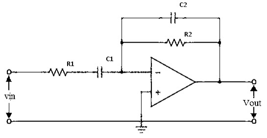
Narrow BPF Circuit
Voltage Gain
The voltage gain of this narrow bandpass filter circuit is given by:
AV = –R2 / R1
Cutoff Frequencies
The lower and upper cutoff frequencies are defined by:
ƒC1 = 1 / (2π × R1 × C1) ƒC2 = 1 / (2π × R2 × C2)
Advantages and Disadvantages of Active Bandpass Filters
Advantages:
- Enables the transmission of signals within a selected frequency range, helping conserve power and reduce noise.
- Useful for isolating desired frequency bands, especially in communications and audio systems.
- Can be customized for specific bandwidth and gain requirements.
Disadvantages:
- Only allows a narrow frequency band to pass, which can be overly restrictive.
- In narrow-band designs, important parts of the signal may be lost, causing output to sound thin or hollow.
- Higher cost compared to passive filters due to active components.
- May require complex circuitry and external power supply.
- Has a limited operating frequency range, depending on component ratings.
Applications of Active Bandpass Filters
Active bandpass filters are widely used in both electronic and optical systems. Common applications include:
- Optical communications: For signal modulation and filtering in satellite, fiber-optic, and data transmission systems.
- Audio processing: Used in sound systems to isolate audible frequencies (typically 20 Hz to 20 kHz).
- Wireless communications: Helps suppress noise and interference, enhancing signal clarity in transmitters and receivers.
- Laser systems: Used in mode-locking and tuning of EDF (Erbium-Doped Fiber) ring lasers and superfluorescent sources.
- Consumer audio gear: Integrated into stereo systems, Dolby surround systems, and distributed speaker networks.
- Signal conditioning: Useful in equalizer circuits, LIDAR, SONAR, and frequency control systems.
- Medical applications: Applied in ECG monitoring, brain signal analysis (EEG), and other neuroscience data acquisition systems.
Where Are Active Bandpass Filters Used?
Active bandpass filters are widely used in telecommunication systems and audio frequency applications (typically ranging from 0 Hz to 20 kHz) such as modems, voice signal processing, and speech analysis. They are also commonly found in wireless transmitters and receivers to filter and isolate signals within a desired frequency range.
What Is the Difference Between Active and Passive Bandpass Filters?
The main difference lies in the use of power and circuit behavior:
- Active bandpass filters require an external power source and include active components like operational amplifiers, allowing them to amplify signals and maintain consistent performance regardless of the connected load.
- Passive bandpass filters are built using only resistors, capacitors, and inductors, and they do not need a power supply. Their performance can vary depending on the load connected to the output.
What Is the Transfer Function of a Bandpass Filter?
The behavior of a bandpass filter can be described using its transfer function, which expresses the ratio of the output signal to the input signal in the frequency domain:
H(ω) = Vout(ω) / Vin(ω)
This function determines how the filter responds to various frequencies and helps define the passband and attenuation characteristics.
What Is a Filter Transfer Function?
The filter transfer function is the Z-transform of a filter's impulse response. It is typically represented as a rational function (i.e., a ratio of polynomials) and is used to model different types of filters such as:
- Low-pass
- High-pass
- Band-reject (notch)
- Bandpass
The transfer function is given by:
Y(z) = H(z) · X(z) = [h(1) + h(2)z⁻¹ + ... + h(n+1)z⁻ⁿ] · X(z)
This equation is fundamental in digital signal processing for analyzing and implementing filter responses.
Summary
In summary, active bandpass filters are essential in electronic systems that require precise frequency selection and signal amplification. They offer benefits such as:
- Stable performance
- High gain
- Reliable filtering
These filters are widely used in communications, radio receivers, audio processing, and biomedical engineering applications. Their ability to selectively allow a specific frequency band while rejecting others makes them indispensable in modern signal processing tasks.
Frequently Ask Questions
What Is an Active Band-Pass Filter?
An active band-pass filter (BPF) is a type of electronic filter that allows signals within a specific frequency range (the passband) to pass through, while attenuating signals below and above that range. Unlike passive filters, it includes active components like operational amplifiers (op-amps) along with resistors and capacitors. Active BPFs can amplify signals and require an external power source for operation.
What Is the Difference Between Active and Passive Band-Pass Filters?
The key differences are:
- Active Band-Pass Filters use op-amps and require power. They offer gain, better frequency control, and are ideal for high-Q (quality factor) applications.
- Passive Band-Pass Filters consist only of resistors, capacitors, and inductors, and do not require external power. They are more suitable for simple, high-power, or low-frequency applications where minimal signal amplification is needed.
What Does BPF Mean on an Amplifier?
A Band-Pass Filter (BPF) in an amplifier allows only a specific range of frequencies to pass, while attenuating signals outside that range. It is typically formed by combining a first-order high-pass filter with a first-order low-pass filter, effectively isolating a desired frequency band for amplification or processing.
What Is an Active Band-Reject Filter?
An active band-reject filter, also known as a notch filter, is designed to attenuate or block a specific band of frequencies while allowing frequencies outside that range to pass. It combines resistors, capacitors, and an op-amp configured to reject unwanted frequencies, making it ideal for eliminating noise or interference at specific frequencies.
Why Do I Need a Band-Pass Filter?
Band-pass filters are critical in many systems, especially wireless communication. In transmitters, they limit the bandwidth of the output signal to prevent interference with other devices. In receivers, they help isolate desired signals from noise or unwanted frequencies, improving signal quality and communication efficiency.
What Are the Benefits of an Active Low-Pass Filter?
Active low-pass filters offer several advantages over passive versions:
- Adjustable cutoff frequencies
- High gain capabilities
- Better signal-to-noise ratio
- Improved frequency precision
- They are ideal for applications where amplification and filtering are required simultaneously.
What Are the Advantages of a Band-Pass Filter?
The primary benefit of a band-pass filter is its ability to selectively allow only a specific range of frequencies, blocking all others. This is especially useful for:
- Noise reduction
- Signal isolation
- Improving signal clarity in audio, communication, and medical devices
What Are the 4 Types of Active Filters?
The four basic types of active filters include:
- Low-Pass Filter (LPF): Passes low frequencies and blocks high frequencies
- High-Pass Filter (HPF): Passes high frequencies and blocks low frequencies
- Band-Pass Filter (BPF): Passes a specific range of frequencies
- Band-Stop Filter (Notch or Band-Reject): Blocks a specific frequency range while passing others
These filters rely on frequency-dependent components such as capacitors and resistors, and often use op-amps for improved performance and tunability.
Related Articles
Guide to Low Dropout (LDO) Regulators and How They Work
ESP32-S3 Development Board: Pinout Diagram, Key Features, Technical Specs
DS18B20 Waterproof Temperature Sensor: Overview, Operation, and Common Uses
BAT54A Schottky Diode: Pinout and Common Uses
Infineon ILD8150E LED Driver IC Overview
LF353N Op-Amp Explained: Pinout, Features, and How It Works
ADXL335 Accelerometer Sensor: Pinout, Specs, Features, and How It Works
Engine Coolant Temperature Sensor: Overview, Function & Circuit Design
Crankshaft Position Sensor: Overview, Circuit Function& Comparison with Camshaft Sensors
Inverting Summing Amplifier: Circuit Diagram,Operation and Formula

Christopher Anderson
Christopher Anderson has a Ph.D. in electrical engineering, focusing on power electronics. He’s been a Senior member of the IEEE Power Electronics Society since 2021. Right now, he works with the KPR Institute of Engineering and Technology in the U.S. He also writes detailed, top-notch articles about power electronics for business-to-business electronics platforms.
Subscribe to JMBom Electronics !


