


ADXL335 Accelerometer Module: Pin Configuration, Features & Internal Components
Catalog
What is the ADXL335 Accelerometer Sensor?How Does the ADXL335 Accelerometer Sensor Work?ADXL335 Accelerometer Pin ConfigurationKey Features and Specifications of the ADXL335ADXL335 Accelerometer Sensor Hardware OverviewDifference Between ADXL335 and ADXL345 Accelerometer ModulesAdvantages of the ADXL335 Accelerometer ModuleDisadvantages of the ADXL335 Accelerometer ModuleApplications of the ADXL335 Accelerometer Sensor ModuleFrequently Asked Questions (FAQ) about the ADXL335 AccelerometerRelated ArticlesHave you ever thought about how your smartphone automatically rotates its screen when you turn it sideways? Or how fitness bands can tell whether you're walking, running, or simply standing still? Behind these smart functions is a compact but powerful device called an accelerometer. These sensors are widely used in modern electronics to detect movement, orientation, and tilt.
One popular and budget-friendly option is the ADXL335 accelerometer module. It’s a small, energy-efficient sensor that can measure acceleration along the X, Y, and Z axes. Because of its low cost and ease of use, it’s a popular choice in DIY electronics and embedded system projects.
In this article, we’ll take an in-depth look at the ADXL335—covering its pin layout, technical specs, internal parts, working principle, how to interface it with microcontrollers, and common real-world applications.
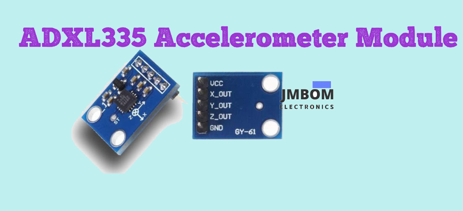
ADXL335 Accelerometer Module
What is the ADXL335 Accelerometer Sensor?
The ADXL335 is a compact, low-power 3-axis accelerometer module developed by Analog Devices. It’s designed to measure acceleration forces along three perpendicular directions—X, Y, and Z axes—and provides corresponding analog voltage outputs that reflect the level of acceleration detected.
This sensor is ideal for detecting motion, tilt, and orientation, making it widely used in applications such as gaming devices, robotics, smartphones, wearables, and more. Thanks to its small form factor and energy efficiency, the ADXL335 is a great choice for projects involving motion sensing, vibration analysis, and tilt detection.
How Does the ADXL335 Accelerometer Sensor Work?
The ADXL335 operates based on the capacitive sensing principle to detect acceleration along the X, Y, and Z axes. This working method relies on measuring changes in capacitance, which occur due to the movement of internal components when subjected to acceleration forces.
Internally, the sensor uses MEMS (Micro-Electro-Mechanical Systems) technology, which includes a small movable mass suspended by springs. When acceleration occurs, the mass shifts slightly, altering the capacitance. These changes are then converted into analog voltage signals, allowing the sensor to track and quantify motion in real-time.
Whenever the sensor experiences acceleration, the internal mass slightly shifts, which alters the capacitance between the moving mass and the fixed structures inside the module. These capacitance changes are then converted into analog voltage signals, allowing the sensor to represent motion as electrical output.
The ADXL335 sensor module provides three separate analog outputs, one for each of the X, Y, and Z axes. Each output voltage is directly proportional to the acceleration along its corresponding axis.
Under zero acceleration conditions, each output typically sits at around 1.65 volts (which is half of a 3.3V supply). When acceleration is applied in a particular direction, the voltage will either increase or decrease depending on the direction and magnitude of the force.
For instance, if a positive acceleration is applied along the X-axis, the X-axis output voltage will rise above the 1.65V baseline. Conversely, a negative acceleration will cause it to drop below this midpoint.
ADXL335 Accelerometer Pin Configuration
The pinout of the ADXL335 accelerometer module is as follows:
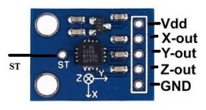
ADXL335 Pin Configuration
ADXL335 Accelerometer Module – Pin Description
| Pin | Name | Description |
|---|---|---|
| 1 | VCC | Power supply input. Connect this to the 5V pin on the Arduino or other microcontroller. |
| 2 | X-Out | Analog output voltage proportional to acceleration along the X-axis. |
| 3 | Y-Out | Analog output voltage proportional to acceleration along the Y-axis. |
| 4 | Z-Out | Analog output voltage proportional to acceleration along the Z-axis. |
| 5 | GND | Ground pin of the module. |
| 6 | ST (Self-Test) | Used to verify proper functionality of the sensor within your application. |
Key Features and Specifications of the ADXL335
- Compact 6-pin accelerometer module
- Available in a low-profile LFCSP_LQ package
- Cost-effective, small, and widely available
- Operating voltage: 3V to 6V DC
- Operating current: Approximately 350 µA
- Measurement range: ±3g (on all three axes)
- Built-in 3-axis motion sensing (X, Y, and Z)
- High sensitivity to minor movements
- No need for external components
- Simple to interface with microcontrollers and analog/digital ICs
- Analog outputs for each axis—ideal for direct ADC input
- Typical sensitivity: ~300 mV/g at 3.0V supply ~330 mV/g at 3.3V supply
- Ratiometric output: Sensitivity and zero-g bias scale with supply voltage
- Operating temperature range: -40°C to +85°C
- Storage temperature range: -65°C to +150°C
- Selectable bandwidth (BW): X and Y axes: 0.5 Hz to 1600 Hz Z axis: 0.5 Hz to 550 Hz
ADXL335 Accelerometer Sensor Hardware Overview
The ADXL335 accelerometer sensor module is built around several key components, including the ADXL335 IC, a 3.3V voltage regulator, and a Self-Test feature. Each of these elements is described in more detail below.
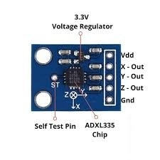
ADXL335 Accelerometer Sensor Hardware
ADXL335 IC
The ADXL335 is a compact, low-power 3-axis accelerometer designed to measure acceleration along the X, Y, and Z axes. It’s commonly used in applications that require tilt detection or motion sensing, such as gaming consoles, mobile devices, DIY electronics, and more.
This IC outputs analog voltages that correspond to the acceleration experienced on each axis. It supports a full-scale measurement range of ±3g, making it suitable for detecting small movements and orientation changes with reliable accuracy.
3.3V Voltage Regulator
The ADXL335 module is equipped with an onboard 3.3V voltage regulator, allowing it to operate with both 3.3V and 5V power sources. This makes it easy to integrate with 5V microcontrollers like the Arduino Uno.
While the ADXL335 sensor itself typically operates at 3.3V, it supports a supply voltage range from 1.8V to 3.6V DC, thanks to the built-in regulator that ensures stable performance.
ADXL335 Self-Test Feature
The ADXL335 module includes a Self-Test (ST) feature that allows you to verify whether the accelerometer is functioning properly. To run a self-test, you simply connect the ST pin to 3.3V. This activates an internal electrostatic force, which causes the tiny mechanical structure inside the sensor to deflect, simulating acceleration.
During a successful self-test, you should observe noticeable changes in the analog output voltages from the sensor's X, Y, or Z pins. Once testing is complete, the ST pin should be either disconnected or connected to GND to return the sensor to normal operation.
Measurement Range
The ADXL335 accelerometer has a measurement range of ±3g, meaning it can detect acceleration up to three times the force of gravity in any direction. If the sensor experiences an acceleration greater than ±3g, it won’t be damaged immediately, but its output will saturate and max out at the ±3g reading.
Despite its ±3g measurement range, the sensor is quite robust and can withstand shock levels up to 10,000g. However, exceeding that level could result in permanent damage.
Ratiometric Output
The ADXL335 provides a ratiometric analog output, which means the output voltage varies linearly with the supply voltage and the sensed acceleration.
- When no acceleration is applied, each output typically sits at half the supply voltage (e.g., ~1.65V for a 3.3V supply).
- At +3g, the output approaches the supply voltage (around 3.3V).
- At -3g, the output drops close to 0V.
This linear scaling makes it easy to interpret readings, especially when connected to ADCs (analog-to-digital converters) in microcontrollers.
Equivalents & Alternatives
Equivalent accelerometer sensors to the ADXL335 include:
- ADXL356
- ADXL345
- MMA8452Q
- LIS3DH
- BMA220
- MPU-6050
Other alternative sensor modules (used for different purposes) include:
- LDR sensor module (light detection)
- IR sensor (obstacle detection)
- TP4056 (Li-ion battery charging)
- DS3231 RTC (real-time clock)
- DRV8825 / TMC2209 / A4988 (stepper motor drivers)
- Joystick module
- EM18 RFID reader
- NEO-6MV2 GPS module
- GLCD 128×64 (graphical LCD)
- HMC5883L (magnetometer)
Interfacing ADXL335 Accelerometer with Arduino Uno
The ADXL335 can be easily interfaced with an Arduino Uno to measure acceleration along the X, Y, and Z axes. The output voltages can be read through the Arduino's analog input pins, and the data can then be displayed on a 16×2 LCD.
Required Components:
- ADXL335 Accelerometer Module
- Arduino Uno Board
- 16×2 LCD Display
- Breadboard
- 5V Power Supply
- Jumper Wires
Wiring the ADXL335 Accelerometer with Arduino Uno
The following describes how to connect the ADXL335 accelerometer sensor, an Arduino Uno, and a 16×2 LCD display (I2C or standard). The Arduino reads analog signals from the sensor and displays the calculated acceleration on the LCD.
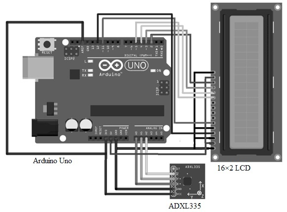
ADXL335 Accelerometer Sensor Interfacing with Arduino Uno
Connection Summary:
| Component Pin | Connects To |
|---|---|
| ADXL335 VCC | Arduino 5V |
| ADXL335 GND | Arduino GND |
| ADXL335 X-Out | Arduino A0 |
| ADXL335 Y-Out | Arduino A1 |
| ADXL335 Z-Out | Arduino A2 |
| LCD GND | Arduino GND |
| LCD VCC | Arduino 5V |
| LCD SDA | Arduino A4 (I2C SDA) |
| LCD SCL | Arduino A5 (I2C SCL) |
⚠️ Make sure the LCD you are using is I2C-compatible. If not, you'll need to wire more pins for standard LCD communication.
Arduino Code for ADXL335 Accelerometer + LCD
This example reads analog values from the ADXL335, calculates acceleration in g units, and displays the results on a 16x2 LCD.
cppCopyEdit#include <LiquidCrystal.h>  // For standard LCD. Use <LiquidCrystal_I2C.h> for I2C LCD

LiquidCrystal lcd(12, 11, 5, 4, 3, 2);  // Adjust pins for non-I2C LCD

int xpin = A0;
int ypin = A1;
int zpin = A2;

int Xrest, Yrest, Zrest;
int Xread, Yread, Zread;
double Gx, Gy, Gz;
int t1;

void setup() {
  Serial.begin(9600);
  lcd.begin(16, 2);  // Initialize 16x2 LCD
  pinMode(13, OUTPUT);

  digitalWrite(13, HIGH);
  delay(1000);

  // Baseline (zero-g) values
  Xrest = analogRead(xpin);
  Serial.print("X baseline: "); Serial.println(Xrest);
  Yrest = analogRead(ypin);
  Serial.print("Y baseline: "); Serial.println(Yrest);
  Zrest = analogRead(zpin);
  Serial.print("Z baseline: "); Serial.println(Zrest);

  digitalWrite(13, LOW);
}

void loop() {
  t1 = millis();
  Serial.print("Time: ");
  Serial.println(t1 * 0.001);  // Time in seconds

  // Read values and offset baseline
  Xread = analogRead(xpin) - Xrest;
  Yread = analogRead(ypin) - Yrest;
  Zread = analogRead(zpin) - Zrest;

  // Convert to g (based on sensitivity ~67.584 LSB/g)
  Gx = Xread / 67.584;
  Gy = Yread / 67.584;
  Gz = Zread / 67.584;

  // Print to Serial Monitor
  Serial.print("Acceleration X: "); Serial.print(Gx);
  Serial.print("  Y: "); Serial.print(Gy);
  Serial.print("  Z: "); Serial.println(Gz);

  // Display on LCD
  lcd.setCursor(0, 0);
  lcd.print("gx:");
  lcd.print(Gx, 2);  // 2 decimal places
  lcd.setCursor(8, 0);
  lcd.print("gy:");
  lcd.print(Gy, 2);
  lcd.setCursor(0, 1);
  lcd.print("gz:");
  lcd.print(Gz, 2);

  delay(1000);
  lcd.clear();
}
Testing and Output
Once everything is connected and the code is uploaded:
- Gently move the sensor in different directions.
- Observe real-time acceleration readings on both the Serial Monitor and the LCD display.
- Values should change as you tilt or shake the sensor in the X, Y, and Z directions.
This setup effectively demonstrates how to read motion data from the ADXL335 and visualize it, making it ideal for robotics, wearable devices, or basic motion detection projects.
Difference Between ADXL335 and ADXL345 Accelerometer Modules
The ADXL335 and ADXL345 are both 3-axis accelerometers, but they differ significantly in terms of communication methods, features, and application suitability. The table below highlights the key differences:
| Feature | ADXL335 | ADXL345 |
|---|---|---|
| Communication Type | Analog output (voltage signals per axis) | Digital output via I2C or SPI |
| Output Format | Analog voltage for X, Y, Z axes | Digital values for X, Y, Z axes |
| Feature Set | Basic — lacks advanced features | Advanced — includes activity detection, free-fall detection, FIFO, etc. |
| Sensitivity and Range Options | Fixed sensitivity, ±3g range | Selectable range: ±2g, ±4g, ±8g, and ±16g |
| Power Modes | No power-saving modes | Supports low power modes and auto-sleep |
| Use Case Suitability | Ideal for simple motion sensing and tilt detection using analog reads | Best for robotics, mobile devices, and digital motion processing |
| Application Complexity | Suitable for basic projects or systems with analog inputs | Suitable for complex applications requiring digital interfacing |
Summary
- Choose the ADXL335 when your project or system requires analog output and simplicity (e.g., tilt sensors, DIY kits, analog microcontrollers).
- Choose the ADXL345 for digital systems, especially if you need high sensitivity, multi-g range, or power-saving features in your application.
Advantages of the ADXL335 Accelerometer Module
- Low Power Consumption: Operates with minimal current—around 320 µA, making it energy efficient.
- Compact Size: Small form factor allows easy integration into various systems and projects.
- Simple Analog Interface: Provides direct analog voltage outputs, simplifying signal processing.
- 3-Axis Measurement: Detects acceleration along the X, Y, and Z axes for comprehensive motion and orientation sensing.
- Versatile: Suitable for a wide range of applications, from gaming to robotics and wearable devices.
- Cost-Effective: Affordable solution for basic accelerometer needs.
- Durable: Can withstand shocks up to 10,000g, ensuring reliability in harsh environments.
- Direct Analog Output: Makes it easy to interface with microcontrollers or electronic systems without complex conversion.
Disadvantages of the ADXL335 Accelerometer Module
- Limited Measurement Range: Only measures acceleration up to ±3g, which may be insufficient for high-impact or fast-motion applications.
- Noise Susceptibility: Analog outputs can be prone to electrical noise, affecting measurement accuracy.
- Requires External Processing: Needs an ADC (Analog-to-Digital Converter) and additional processing to interpret analog signals, adding system complexity and cost.
- Zero-G Drift: The zero-g output can drift over time, especially with temperature variations, requiring periodic calibration or offset correction.
- Limited Yaw Detection: Cannot accurately measure rotation (yaw) around the Z-axis alone, as such rotation doesn’t produce acceleration changes on the other axes.
Applications of the ADXL335 Accelerometer Sensor Module
The ADXL335 accelerometer is widely used across various fields due to its accuracy, compact size, and low power consumption. Common applications include:
- Handheld Devices: Used for intelligent power management, 6D orientation detection, and free-fall detection to enhance user experience and device safety.
- RC Systems, Robotics, and Flight Platforms: Helps maintain stability and balance by continuously detecting motion and orientation changes.
- GPS Navigation Systems: Collects real-time data on acceleration and movement to improve positioning accuracy.
- Impact Recognition and Logging: Detects and records the force and duration of impacts during accidents for safety monitoring.
- Virtual Reality (VR) Headsets and Game Controllers: Provides input based on tilt and motion, enabling immersive and responsive user interaction.
- Motion-Activated Controls: Triggers actions such as turning on displays or lights based on detected movement.
- Vibration Monitoring and Compensation: Used to monitor machinery vibrations, enhancing reliability and performance.
- Other Devices: Commonly found in mobile phones, smartwatches, fitness bands, automotive systems, and digital cameras.
- Specialized Applications: Measures seismic activity for earthquake detection, supports internal navigation systems (INS), and monitors rotating machinery.
In summary, the ADXL335 is a versatile and widely adopted accelerometer sensor module. Its small size, low power consumption, and ability to measure both static and dynamic acceleration make it an excellent choice for numerous projects and industries.
Frequently Asked Questions (FAQ) about the ADXL335 Accelerometer
What is the use of the ADXL335 accelerometer?
The ADXL335 is a 3-axis analog-output accelerometer with a measurement range of ±3g. It outputs analog voltages proportional to acceleration and can detect both:
- Static acceleration (like gravity) for tilt sensing
- Dynamic acceleration caused by motion, shock, or vibration
How do I check if an accelerometer is working?
A simple way to test it is using a smartphone or the sensor in a DIY project:
- Place the device flat on a table (screen up).
- Quickly lift it upward and gently place it back down.
- Flip the device screen-down and repeat. You should observe spikes in acceleration readings along the same axis, confirming the sensor is responsive.
What voltage range does the ADXL335 output for acceleration?
The ADXL335 typically outputs voltages in the range of 0 to 3.3V, depending on the supply voltage and sensed acceleration. At 0g, each axis typically outputs around 1.65V (half the supply voltage), and this changes linearly with acceleration.
What is the primary purpose of an accelerometer?
An accelerometer measures acceleration — the rate of change of velocity — or vibration. When subjected to motion, a small internal mass shifts and generates an electrical signal (e.g., via a piezoelectric effect or capacitive sensing), which is proportional to the force experienced. This allows detection of movement, orientation, shocks, or tilt.
Is the ADXL335 analog or digital?
The ADXL335 is an analog accelerometer. It provides continuous analog voltage outputs for the X, Y, and Z axes, unlike digital accelerometers which transmit data over I2C or SPI.
What kind of data does an accelerometer provide?
Accelerometers provide acceleration data along one or more axes. This includes:
- Changes in speed or direction
- Vibrations, shocks, or impacts
- Orientation, such as tilt or free-fall detection The data can be used to detect motion events like hard braking, sudden acceleration, or rotation.
How can I fix accelerometer sensor issues?
Common causes of accelerometer issues include:
- Low-frequency noise or bias, especially in cheaper sensors
- Loose, dirty, or corroded connections To fix these:
- Clean or replace cables or connectors
- Ensure proper grounding and power supply
- Recalibrate the sensor if possible, especially if offset drift is observed
What is the difference between the ADXL335 and ADXL345?
| Feature | ADXL335 | ADXL345 |
|---|---|---|
| Output Type | Analog voltage | Digital (I2C / SPI) |
| Range | ±3g | Selectable ±2g/±4g/±8g/±16g |
| Advanced Features | Basic | Free-fall detection, tap sensing, FIFO buffer, power modes |
| Resolution | Fixed | Higher resolution |
| Applications | Simple analog systems | Smart devices, robotics, wearables, data logging |
Is an accelerometer a sensor?
Yes. An accelerometer is a type of sensor that measures acceleration — the rate of change of velocity over time. It is widely used in:
- Automobiles (airbags, ABS systems)
- Smartphones (screen rotation, pedometers)
- Wearables (fitness tracking)
- Industrial machinery (vibration analysis)
- Aerospace and robotics
Related Articles
Active Bandpass Filter: Overview, Types,Q Factor & Applications
Passive High-Pass Filter: Overview, Circuit Design & Transfer Function
Differential Pressure Sensors: Working Principle, Interfacing,Testing Methods and Common Issues
Voltage Amplifier: Circuit Design, Gain, vs. Power Amplifier, and Key Applications
Resistor-Transistor Logic (RTL):Operation, Features, and Applications
Diode-Transistor Logic (DTL): Circuit Design,Truth Table, and Applications

Amanda Miller
Amanda Miller is a senior electronics engineer with 6 years of experience. She focuses on studying resistors, transistors, and package design in detail. Her deep knowledge helps her bring innovation and high standards to the electronics industry.
Subscribe to JMBom Electronics !


