


Guide to Safety Relays
Catalog
What Is a Safety Relay?Working Principle of Safety RelaysFault DetectionSafety Relay CircuitsOperationSafety Relay Wiring DiagramOperation of the Safety RelaySafety Relays vs. Standard RelaysSafety RatingsAdvantages and DisadvantagesApplicationsWhat is the HSN Code for a Safety Relay?What is the Purpose of a Safety Relay?Related ArticlesA relay is one of the most critical components in an electrical panel – an electromechanical switch that activates its mechanical contacts when electrically energized. Essentially, it isolates two electrical circuits while acting as the connecting contact between them. Relays come in a variety of types, each engineered for specific use cases, and safety relays are a key category among them, featuring a straightforward design and intuitive operation.
Thanks to their high reliability, compact construction and other advantages, safety relays are widely utilized and have become indispensable components in environments where safety functions are non-negotiable, such as power plants and industrial machinery. This article provides a concise overview of safety relays, including their operating principles and practical applications.
What Is a Safety Relay?
A safety relay is an electromechanical component designed to execute safety functions in industrial and machinery systems. It activates in the event of a hazard, mitigating risks to a safe and acceptable level. When a fault occurs, the relay triggers a reliable, secure response—and each unit is engineered to monitor a specific safety function.
Safety relays deliver efficient, straightforward compliance with industry safety standards, ensuring the safe operation of equipment and a long service life for the systems they protect.
A diagram of a safety relay is shown below.
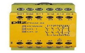
Safety Relay
Safety relays function to halt motion in a safe, controlled manner, monitor the position of movable guards and emergency stop circuits, and interrupt closing motions for access points.
Working Principle of Safety Relays
The working principle of a safety relay is to detect faulty contactors, defective actuators, and wire breaks by transmitting electrical pulses through the wiring system. Safety relays feature mechanically linked contacts with an interlocking design: if a normally open (NO) contact remains closed, a normally closed (NC) contact cannot close simultaneously. By measuring electrical current flow, these relays reliably detect welded contact sets and wire breaks. They excel at consistently monitoring signals from safety devices and triggering an immediate shutdown in emergency situations.
Fault Detection
Safety relays typically detect four primary types of faults: wire breaks, faulty contactors, defective safety actuators, and timing irregularities.
They identify wire breaks, faulty actuators and contactors by sending electrical pulses through the wiring, and verify wire breaks and welded contact sets via current flow measurement—timing detection is also integrated to complete this fault-checking process.
Timing is a key fault detection method employed by safety relays, with a common application in verifying redundant contact sets on safety actuators. If the two contact sets of the relay fail to close within a specified time interval, the auto-reset function will be disabled.
Safety Relay Circuits
A safety relay is typically a complete integrated unit consisting of three relays with all associated contact configurations. A circuit diagram of the safety relay is shown below. In this setup, the safety contact is connected between points A and B, and the supply voltage is most commonly 110V AC.
A reset pushbutton is connected between points C and D. Terminals E and F are wired to a controller (e.g., a PLC) for monitoring purposes, while terminals G and H are integrated into the safety circuit to actuate the final contactors that supply power to the motor.
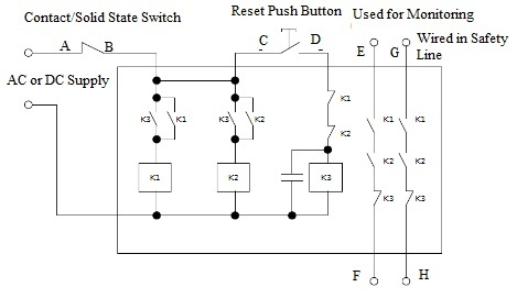
Safety Relay Structure
Operation
When AC or DC power is supplied to the circuit, all three relays (K1, K2, K3) are de-energized. The terminals connected to the safety circuit remain open and serve as monitoring points. To activate the safety relay, the safety device’s contact must first close to energize points B and C, after which the reset pushbutton is pressed.
Pressing the reset pushbutton energizes relay K3 by activating point D. Once energized, K3 closes its normally open (NO) contacts, which in turn energizes relays K1 and K2. This causes K1 and K2 to activate and self-latch via their dedicated self-latching contacts.
Releasing the reset pushbutton de-energizes K3, while K1 and K2 remain energized—keeping terminals EF and GH closed. If the safety device’s contact opens, point B is de-energized, which shuts down K1 and K2. This opens the connections at terminals EF and GH, interrupting the safety circuit and tripping the main contactor. A capacitor is incorporated into the design to provide an off-delay for relay K3, ensuring K1 and K2 have adequate time to energize and achieve self-latching.
Safety Relay Wiring Diagram
The safety relay wiring diagram is shown below. This section outlines the wiring process for connecting a safety relay to a dual-channel emergency stop circuit.
To power on the safety relay, supply 24V DC to terminal A1, with terminal A2 connected to ground (GND). Next, connect the two sets of normally closed (NC) contacts to the emergency stop button: the first contact of the emergency stop button is wired between terminals S11 and S12, and the second contact between terminals S21 and S22.
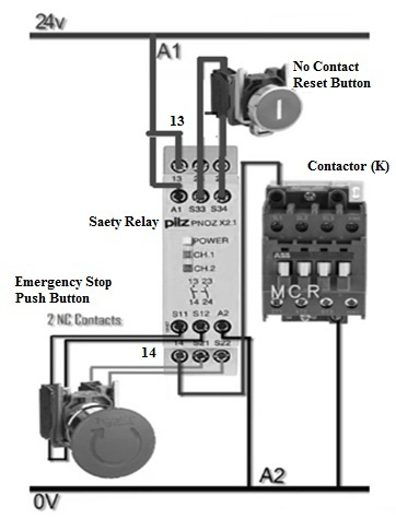
Wiring Diagram of Safety Relay
The relay then begins monitoring the normally closed (NC) contacts of the emergency stop push button on Channel 1 and Channel 2. Next, connect a dedicated push button for manual reset of the safety relay, wiring its normally open (NO) contact to terminals S33 and S34 of the safety relay. Finally, connect a master control relay (MCR) or master control contactor to the safety relay—activate the contactor using the NO contact at terminals 13 and 14 of the safety relay.
Operation of the Safety Relay
Initiate the safety relay by supplying 24V DC power, at which point the power LED illuminates. Press the reset push button, and the relay will energize the master control contactor. The relay then starts continuous monitoring of the emergency stop push button’s contacts on Channel 1 and Channel 2.
If the emergency stop push button is pressed, it opens the NC contacts on Channel 1 and Channel 2 at the safety relay’s S11/S12 and S21/S22 terminals, and the Channel 1 and Channel 2 indicator LEDs turn off simultaneously. This causes the safety relay’s NO contacts at terminals 13 and 14 to open, de-energizing the master control contactor and shutting it down.
Reset the physical emergency stop push button first—this wiring configuration features no automatic reset for the safety relay. A manual reset is required: press the dedicated reset push button once. Upon pressing the reset button, Channel 1 and Channel 2 resume monitoring the emergency stop push button’s contacts, and the master control contactor energizes and restarts operation immediately.
Safety Relays vs. Standard Relays
This section outlines the key differences between safety relays and standard (general-purpose) relays, as summarized in the comparison below:
Safety Relays
- Engineered specifically to implement and monitor industrial safety functions
- Typically available in larger form factors
- Does not feature C-type contacts
- Equipped with force-guided contacts (e.g., locked, positive, or captive-guided contacts)
- Manufactured in industry-specified safety colors (e.g., yellow)
- Larger physical dimensions (common sizes include 17.5 mm, 22.5 mm, etc.)
- Integrate multi-functional capabilities: switching, status indication, and circuit protection
- Primarily designed for safety-critical switch configuration and control
- Cost point is up to 15 times higher than standard relays
- Exclusively used in safety-critical industrial applications
Standard Relays
- An electromechanical switch operated by low-power signals to control high-power circuits
- Compact, small form factors
- Features C-type contacts
- Constructed with standard electrically conductive metal contact components
- No industry-specified color coding
- Smaller physical dimensions relative to safety relays
- Single primary function: basic switching in control circuits
- Designed for general contact connection and circuit switching
- Economical and cost-effective
- Versatile for use in nearly all general automation applications
Safety Ratings
When selecting a safety relay, critical specifications such as safety ratings must be taken into account. Safety relays are classified into four distinct categories per the EN954-1 standard, and buyers should first define the safety requirements of their specific application, then select a product with a minimum rating that meets those needs. Notably, safety relays with higher safety ratings typically come with a higher cost point.
- Category 1: Devices may cease operation following a single fault. They are designed with fixed components and operating principles to minimize the likelihood of fault occurrence.
- Category 2: Devices may experience functional failure if a fault occurs between two test cycles.
- Category 3: Devices remain operational in the event of a single fault.
- Category 4: Relays maintain normal operation even when multiple faults occur.
Advantages and Disadvantages
Advantages
Safety relays offer the following key advantages:
- Higher operational consistency compared to standard relays
- Cost-effective relative to other specialized safety relays
- Simple in design and operation
- No software programming required
- Deliver enhanced safety protection for energizing and de-energizing circuit components
- Protect both industrial machinery and operators, reducing equipment maintenance and replacement costs
- Support both automatic and manual activation modes
- Fast operating time of 45ms
- Recovery time of 1 second
- Wide ambient temperature operating range: -20˚C to 55˚C
Disadvantages
The primary disadvantages of safety relays are as follows:
- Complex wiring in large-scale systems
- Difficult system restart and fault diagnosis following a shutdown
- Complete rewiring required for any subsequent system modifications
- Relatively slow operating speed
- Susceptible to environmental factors
- May generate operational noise
- Limited to use in low-current circuits
Applications
Safety relays serve the following key applications across industrial and everyday use cases:
- Detect faults at input contacts in safety circuits in the event of an earth fault
- Are widely utilized in industrial automatic control circuits
- Act as electromechanical switching devices designed to prevent malfunctions during high-risk switching operations
- Are integrated into industrial machinery and equipment to elevate the machine’s safety rating
- Continuously monitor safety input devices and disable machine operation if hazardous conditions are detected
- Are deployed in all safety-critical industrial applications
- Are commonly used with core safety components including safety gates, emergency stop circuits, light curtains, safety mats, two-hand control systems, interlocked gates and foot-operated switches
- Provide protective functionality in daily use to prevent electric shocks and equipment overheating
- Are suitable for both basic and advanced safety solutions where safety devices must be verified in compliance with functional safety standards
What is the HSN Code for a Safety Relay?
The Harmonized System of Nomenclature (HSN) is a standardized system for the systematic classification of goods. Developed by the World Customs Organization (WCO), it is the global benchmark for commodity naming and classification. The HSN Code for safety relays is 85364900.
What is the Purpose of a Safety Relay?
The primary purpose of a safety relay is to protect both machine operators and industrial equipment, thereby reducing costly equipment replacement and maintenance expenses.
In summary, this overview covers the core fundamentals of safety relays. As regulatory requirements for industrial safety continue to evolve and efforts to protect operators from workplace hazards intensify, safety relays have become one of the most widely used components in safety systems. These relays detect faults in input/output devices as well as internal component failures, and while they are a key single component in safety control systems, all components within a safety control system must be properly selected and implemented to achieve the required level of operator protection.
A follow-up question for further exploration: What is a protective relay?
Related Articles
Diode Dynamics: Real-World Behavior in Fast Power and RF Circuits

Christopher Anderson
Christopher Anderson has a Ph.D. in electrical engineering, focusing on power electronics. He’s been a Senior member of the IEEE Power Electronics Society since 2021. Right now, he works with the KPR Institute of Engineering and Technology in the U.S. He also writes detailed, top-notch articles about power electronics for business-to-business electronics platforms.
Subscribe to JMBom Electronics !


