


Resistor Power Rating: Operation and Applications
Catalog
What is the Power Rating of a Resistor?How to Determine the Power Rating of a ResistorHow to Measure the Power Rating of a ResistorElectrical Power UnitsExample ProblemsChartCurrent Ratings at 9V SupplyUses of Resistor Power RatingRelated ArticlesCurrent flows through a resistor when a voltage is applied across it, causing electrical energy to be dissipated as heat. The greater the current flow, the more heat the resistor generates — this behavior is defined by the resistor’s power rating.
Resistors are typically specified by their resistance value and their power rating, measured in watts. The amount of power a resistor can safely dissipate depends on its physical size. Every resistor has a maximum power rating, which is determined by its dimensions.
A larger surface area allows heat to be dissipated safely into the surrounding air. This article provides an overview of resistor power ratings and how to calculate them.
What is the Power Rating of a Resistor?
The power rating of a resistor is defined as the maximum amount of power that a resistor can safely dissipate during normal operation.
It is one of the key specifications for a resistor, and is often referred to as its wattage rating.
According to Joule’s First Law, the electrical power dissipated in a resistor is equal to the product of the voltage across the resistor and the current flowing through it.
Power Rating of Resistor
For example, if a resistor has a power rating of ½ watt, this indicates the maximum power it is designed to handle continuously. If the power applied exceeds this rating by even a small percentage, the resistor will overheat and burn out.
How to Determine the Power Rating of a Resistor
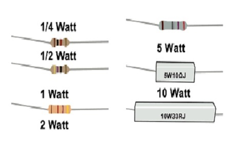
The power rating of a resistor can generally be identified by its package size. Standard through‑hole resistors are commonly available with ¼ W or ½ W ratings. Power resistors, on the other hand, usually have their power rating clearly marked, such as 3 W, 5 W, and 25 W, and are offered in resistance values including 0.1 Ω, 2 Ω, 3 Ω, and 22 kΩ.
For surface‑mount (SMD) resistors, power ratings are determined by their physical dimensions. 0402 and 0603 package sizes are typically rated at 1/16 W, while 0805 resistors are usually rated at 1/10 W.
The power rating can also be calculated using the electrical power formula:
P=V×I
where V is voltage and I is current.
Using Ohm’s Law V=I×R, this formula can be rewritten as:
P=I2R=RV2
How to Measure the Power Rating of a Resistor
The power rating of a resistor can be calculated using the standard formulas below:
P=V×I
P=I2R
P=RV2
Power rating is measured in watts (W), the standard unit of power.
In general, larger resistors can handle higher power levels. As the wattage rating increases, the cost of the resistor also rises. Power ratings typically range from 1/8 watt up to kilowatt levels.
Electrical Power Units
The units of electrical power, along with their symbols, values, and abbreviations, are shown in the table below.
| Unit | Symbol | Value | Abbreviation |
|---|---|---|---|
| milliwatt | mW | 1/1000 watt | 10⁻³ W |
| kilowatt | kW | 1000 watts | 10³ W |
| megawatt | MW | 1 000 000 watts | 10⁶ W |
Example Problems
Below are example problems involving resistor power ratings.
Example 1
A fixed resistor has a voltage of 10 V across its terminals, and the current flowing through it is 40 mA.
What is the power rating of the resistor in watts?
Given:
V=10 V
I=40 mA=0.04 A
Using the power formula:
P=V×I
P=10×0.04=0.4 W
The power rating is 0.4 W (400 mW).
Example 2
A resistor is rated at 0.5 W.
Calculate the maximum safe current that can flow through the resistor.
Given:
P=0.5 W
Starting from the power equation:
P=I2R
Rearranging for current:
I=RP
Substitute the values:
I=18000.5≈0.0167 A=16.7 mA
The maximum safe current is approximately 0.0167 A or 16.7 mA.
Chart
The physical size of a resistor mainly depends on its power or wattage rating.
Larger resistors can handle higher wattages.
The resistor power rating chart below provides information about the power ratings and corresponding physical sizes of various resistors.
Resistor Size
Power Rating in Watts
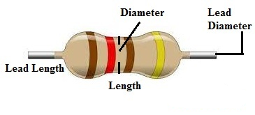
| Power Rating | Diameter (mm) | Length (mm) | Lead Length (mm) | Lead Diameter (mm) |
|---|---|---|---|---|
| 1/8 W | 1.8 | 3 | 28 | 0.45 |
| 1/4 W | 2.5 | 6.5 | 28 | 0.6 |
| 1/2 W | 3.2 | 8.5 | 28 | 0.6 |
| 1 W | 5 | 11 | 28 | 0.8 |
| 2 W | 5.5 | 15 | 35 | 1 |
| 3 W | 6 | 17 | 35 | 1.1 |
| 5 W | 7.5 | 24 | 38 | 1.2 |
Current Ratings at 9V Supply
When connected to a 9 V voltage source, the maximum safe current for each resistor is as follows:
- A 1/8-watt resistor (dimensions 1.8 × 3 × 28 mm) can handle up to 13.88 mA.
- A 1/4-watt resistor (dimensions 2.5 × 6.5 × 28 mm) can handle up to 27.77 mA.
- A 1/2-watt resistor (dimensions 3.2 × 8.5 × 28 mm) can handle up to 55.55 mA.
- A 1-watt resistor (dimensions 5 × 11 × 28 mm) can handle up to 111.11 mA.
- A 2-watt resistor (dimensions 5.5 × 15 × 35 mm) can handle up to 222.22 mA.
- A 3-watt resistor (dimensions 6 × 17 × 35 mm) can handle up to 0.4 A.
- A 5-watt resistor (dimensions 7.5 × 24 × 38 mm) can handle up to 0.8 A
Uses of Resistor Power Rating
The key applications and importance of resistor power ratings are summarized below.
A resistor’s power rating defines the maximum power it can safely handle during normal operation.
This is a critical parameter when selecting a resistor for a specific application. The primary role of a resistor is to limit current flow in a circuit by dissipating excess electrical energy as heat.
Every resistor has a maximum power dissipation rating, which is the highest power it can convert to heat without being damaged. Exceeding this rating will cause the resistor to overheat and fail.
This completes our overview of resistor power ratings, including worked examples.
Resistors are used in a wide range of circuits, but not all types are suitable for every application. Resistor selection depends on several parameters, including color code and power rating.
Resistor color codes indicate resistance value, tolerance, and sometimes voltage rating.
The power rating, on the other hand, is used to protect both the resistor and the entire circuit from damage.
Here is a question for you:
What is a resistor with a power rating above 5 W commonly called?
Related Articles
Diode Dynamics: Real-World Behavior in Fast Power and RF Circuits

Christopher Anderson
Christopher Anderson has a Ph.D. in electrical engineering, focusing on power electronics. He’s been a Senior member of the IEEE Power Electronics Society since 2021. Right now, he works with the KPR Institute of Engineering and Technology in the U.S. He also writes detailed, top-notch articles about power electronics for business-to-business electronics platforms.
Subscribe to JMBom Electronics !


