


Air Flow Sensor: Circuit, Operation, Types, Wiring, Interfacing & Applications
Catalog
What Is an Air Flow Sensor?How Does an Air Flow Sensor Work?Air Flow Sensor Circuit DiagramTypes of Air Flow SensorsAir Flow Sensor Wiring DiagramAir Flow Sensor Interfacing with ArduinoAdvantages and Disadvantages of Airflow SensorsApplications and Uses of Airflow SensorsFrequently Ask QuestionsRelated ArticlesModern vehicles rely on a wide range of sensors to manage performance and ensure protection against damage. These include sensors such as MAP (Manifold Absolute Pressure), engine knock, throttle position, camshaft position, airflow, engine speed, oxygen, voltage sensors, and more. Among them, the airflow sensor plays a vital role in engine management.
The first plug-in mass airflow (MAF) sensor was developed by DENSO in 1996. Since then, ongoing advancements in automotive technology have driven improvements in high-performance vehicle components. The air flow sensor measures the volume of air entering the engine and sends this information to the vehicle’s ECU (Engine Control Unit), which adjusts the air-fuel mixture for optimal efficiency and performance.
This article provides a comprehensive overview of the airflow (or MAF) sensor, explaining how it works, the different types available, and where it is used.
What Is an Air Flow Sensor?
An air flow sensor is an automotive sensor designed to measure the rate of air entering a system, such as an internal combustion engine, an HVAC unit, or industrial machinery. In vehicles, the ECU (Engine Control Unit) uses this data to calculate the appropriate amount of fuel to inject, ensuring the correct air-fuel ratio for efficient combustion.
Commonly known as a Mass Air Flow (MAF) sensor or simply an air meter, this device converts the incoming air volume into a voltage signal that represents engine load. Since air density can vary based on temperature, pressure, and humidity, the sensor plays a critical role in adapting engine performance to changing conditions.
How Does an Air Flow Sensor Work?
The airflow sensor operates by detecting changes in electrical resistance caused by airflow across a heated wire or film. As air passes over the heated element, it cools it down, altering its resistance. This change is then converted into an electrical signal and sent to the ECU. The ECU uses this signal to determine how much fuel needs to be delivered to the engine for optimal performance and emissions control.
The airflow sensor typically consists of two wires—one electrically heated and the other unheated. When the heated wire is maintained at a constant temperature and placed in the path of incoming air, it begins to cool down in proportion to the speed of the airflow.
As the temperature difference between the heated and unheated wires changes, the sensor adjusts the current flowing through the heated wire to maintain its temperature. This variation in current is then sent to the ECU, where it is converted into a voltage or frequency signal that represents the airflow rate.
Air Flow Sensor Circuit Diagram
Airflow detection plays a key role in many electronic circuits. Below is a simple airflow sensor circuit designed to sense the presence of airflow. Unlike other designs, this circuit doesn’t require an RTD (Resistance Temperature Detector) or a Zener diode. Instead, it uses the filament of a standard AC bulb, along with a few other components, to detect airflow.
The main components needed for this circuit include:
- LM358 IC
- LM7805 voltage regulator
- Resistors: 680Ω, 100Ω, 330Ω, and 10K
- 100µF capacitor
- 50K variable resistor (potentiometer)
- LED
- 12V power supply
- Incandescent bulb (filament used for sensing)
- DC fan
- Push button
- Jumper wires
Follow the circuit diagram below to connect all the components properly.
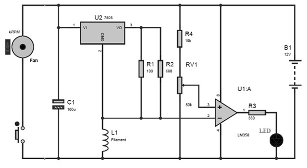
Air Flow Sensor Circuit Diagram
Working Principle
The circuit shown below is a simple airflow sensor that operates using a 12V DC power supply. The key component in this design is the filament of an incandescent bulb, which plays a critical role in detecting airflow by producing a voltage change when exposed to moving air.
The bulb filament has a Negative Temperature Coefficient (NTC), meaning its resistance decreases as its temperature increases. When no air is flowing, the filament heats up slightly and its resistance stays low. However, when airflow passes over the filament, it cools down, causing its resistance to increase.
This change in resistance results in a voltage variation across the filament. This voltage change is detected by the LM358 IC, which is configured in comparator mode. The IC compares the voltage across the filament to a reference voltage. If a sufficient difference is detected (indicating airflow), the comparator outputs a low signal.
- The potentiometer is used to calibrate the circuit sensitivity.
- The LED acts as an indicator to show the presence of airflow.
- The push button and DC fan are included to manually generate airflow across the filament.
This simple circuit effectively translates a physical airflow event into a usable electronic signal.
Types of Air Flow Sensors
There are several types of airflow sensors, each designed for specific applications. Below is an overview of some common types.
Volume Air Flow Sensor
A volume air flow sensor measures the flow rate of air by volume and is commonly used for tasks such as filter monitoring, differential pressure measurement, and liquid level detection. These sensors are widely used in:
- Medical equipment
- Clean rooms
- HVAC and air conditioning ducts
- Ventilation systems
- Spray booths
- Industrial kitchens
Their main function in these environments is to monitor air filters, measure airflow levels, or control devices like frequency converters based on airflow changes.
Volume AFS
MAF Sensor
The MAF sensor, or Mass Air Flow sensor, is used in vehicles to measure the mass flow rate of air entering the engine. This information is crucial for determining the correct amount of fuel to inject for optimal combustion.
The Engine Control Unit (ECU) relies on accurate air mass data to maintain the proper air-fuel ratio. Since air density can vary with pressure, temperature, and environmental conditions (such as altitude or forced induction), the MAF sensor provides a more precise measurement than a volumetric flow sensor.
Because of these variations, MAF sensors are particularly useful in automotive applications to calculate the actual amount of air entering each cylinder, ensuring better fuel efficiency and engine performance.
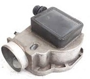
Vane Type MAF Sensor
Vane-Type Mass Air Flow Sensor
A vane-type mass air flow sensor uses a spring-loaded metering vane placed in the path of the incoming air to measure airflow. As air flows through the sensor, it pushes against the vane, causing it to rotate or deflect against the spring tension.
The amount of deflection is directly related to the volume of air passing through the sensor. This mechanical movement is converted into an electrical signal—typically a voltage—via a potentiometer connected to the vane. The resulting voltage is then sent to the ECU to determine the airflow rate.
This type of sensor provides a simple yet effective way to measure air intake and is commonly used in older automotive systems.
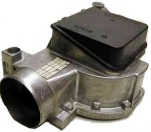
Vane Type MAF Sensor
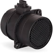
Hot-Wire Air Flow Sensor
The hot-wire air flow sensor is widely used in modern vehicles to measure the mass of air entering the engine. It plays a crucial role in engine management by providing real-time airflow data to the ECU (Engine Control Unit), which uses this information to optimize the air-fuel mixture for efficient combustion.
This sensor measures both the volume and density of the incoming air. These measurements are essential for the ECU to accurately determine how much fuel should be injected into the combustion chambers to maintain the ideal air-fuel ratio.
Since air density varies with altitude, temperature, and forced induction (like turbocharging or supercharging), the hot-wire sensor offers a more accurate reading than traditional volumetric flow sensors. This makes it especially effective for precisely calculating the amount of intake air for each cylinder under varying operating conditions.
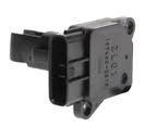
Hot-Wire Air Flow Sensor
Air Flow Sensor Wiring Diagram
The wiring of a Mass Air Flow (MAF) sensor can vary depending on the vehicle’s make, model, year, and system design. Typically, MAF sensors come in 3-wire, 4-wire, or 5-wire configurations. Below is an explanation of a 4-wire MAF sensor wiring diagram, one of the most common setups.
4-Wire MAF Sensor Connections:
- 12V Power Supply (Hot-Wire) This wire provides power to heat the sensing element. It is connected to a fuse and relay in the vehicle’s fuse box.
- MAF Signal Wire This wire sends the airflow data (as a voltage signal) to the vehicle’s ECU. It reflects the amount of air entering the engine.
- MAF Ground (GND) A common ground connection shared by both the MAF sensor and the ECU, ensuring signal integrity.
- IAT Signal (Intake Air Temperature) Many MAF sensors integrate an Intake Air Temperature (IAT) sensor. This wire sends the intake air temperature reading to the ECU, which helps fine-tune fuel delivery based on air density.
Working Principle of the Signal Circuit:
Inside the sensor, the signal circuit monitors the current flowing through the hot wire. As airflow changes, the current also changes, and this variation is converted into a voltage signal. The voltage is then transmitted to the ECU via the MAF signal wire. The IAT signal is handled separately within the same sensor housing, providing temperature feedback for more accurate engine control.
Air Flow Sensor Interfacing with Arduino
The airflow sensor (also known as a thermal anemometer or wind sensor Rev. P) is an affordable and Arduino-friendly device. It includes built-in hardware compensation for ambient temperature, using PTC thermistors to improve accuracy. This sensor can detect strong winds—up to hurricane-force speeds—without saturating, with a measurement range from 0 to 150 mph.
It outputs a voltage up to 3.3V, making it compatible with most Arduino boards and other microcontrollers.
How It Works
The sensor operates on the thermal anemometer principle, often called the hot-wire method. It heats an element and monitors the power required to maintain its temperature. When airflow increases, the heated element cools down faster, requiring more power to keep warm. When there is no wind, the heating element remains at a steady temperature.
By measuring the change in current and power to the heating element, the sensor can accurately determine wind speed.
Technical Specifications
- Operating Voltage: 4 to 5 volts
- Current Consumption: 20 to 40 mA
- Wind Speed Range: 0 to 60 mph
Pin Description
The airflow sensor (or wind sensor) Rev. P version features a 5-pin configuration as described below:
- GND: Common ground pin for the sensor, connected to the circuit’s ground.
- V+: Power input pin, typically connected to the Arduino’s voltage supply.
- OUT (or Ao): Analog output pin that provides a voltage signal proportional to the airflow, representing the current flowing through the sensor.
- TMP: Temperature output pin, acting as a voltage divider formed by a thermistor and resistor. The voltage at this pin is higher at lower temperatures and decreases as temperature rises.
- RV: Reference voltage pin providing a stable voltage (above 1.8V at room temperature) used for sensor calibration. This voltage is unaffected by the calibration potentiometer and is typically left unconnected in most Arduino setups.
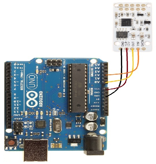
Air Flow Sensor Interfacing with Arduino Board
Typical Arduino Connections:
- Connect the sensor’s GND pin to the Arduino’s GND pin.
- Connect the sensor’s V+ pin to the Arduino’s Vin pin.
- Connect the sensor’s OUT pin to Arduino’s A0 (analog input 0) pin.
- Connect the sensor’s TMP pin to Arduino’s A2 (analog input 2) pin.
- The sensor’s RV pin is usually not connected in standard interfacing.
Arduino Code for Air Flow Sensor Interfacing
cppCopyEditconst int OutPin = A0;    // Wind sensor analog pin connected to sensor "OUT" pin
const int TempPin = A2;   // Temperature sensor analog pin connected to sensor "TMP" pin

void setup() {
  Serial.begin(9600);     // Initialize serial communication at 9600 baud
}

void loop() {
  // Read raw wind sensor analog value
  int windADunits = analogRead(OutPin);

  // Calculate wind speed (MPH) based on sensor calibration data
  // Note: This formula is derived from wind tunnel testing and regression analysis
  // It currently does not account for temperature compensation
  float windMPH = pow(((float(windADunits) - 264.0) / 85.6814), 3.36814);
  Serial.print(windMPH);
  Serial.print(" MPH\t");

  // Read raw temperature sensor analog value
  int tempRawAD = analogRead(TempPin);

  // Convert raw analog reading to temperature in Celsius
  // Using sensor's voltage output formula: Vout = (TempC * 0.0195) + 0.400
  // Rearranged to solve for TempC based on datasheet parameters
  float tempC = (((float(tempRawAD) * 5.0) / 1024.0) - 0.400) / 0.0195;
  Serial.print(tempC);
  Serial.println(" C");

  delay(750);  // Wait 750 milliseconds before next reading
}
Additional Notes
- The Arduino board is powered by a 9V external power supply, and the sensor receives power from the Arduino’s Vin pin.
- Upload this code to the Arduino and open the Serial Monitor to observe the wind speed (in MPH) and temperature (in °C) readings from the sensor.
- The analog output from the sensor is logarithmic, which allows it to detect very low airflow levels accurately while avoiding saturation up to around 60 mph wind speed.
- The voltage signal from the sensor’s analog output pin (A0) corresponds directly to wind speed, based on the hot-wire anemometer principle.
- This method works well for low to moderate wind speeds and is especially suited for measuring indoor airflow direction and velocity.
Advantages and Disadvantages of Airflow Sensors
Advantages
- Easy to install: Airflow sensors are generally straightforward to set up.
- Cost-effective: They are relatively affordable compared to other sensor types.
- Comprehensive measurement: These sensors measure both total and static air pressure as well as average air velocity.
- Variety of designs: Multiple design options are available to suit different applications.
- Low maintenance: With few or no moving parts, these sensors require minimal upkeep.
- Widely used: They are among the most common sensors for measuring airflow in automotive and industrial systems.
Disadvantages
- Sensitive to contaminants and vibration: Improper installation can lead to issues caused by gas inclusions and vibrations.
- Relatively costly: While affordable, they can be more expensive than some simpler sensors.
- Reduced engine performance: Faulty airflow sensors can restrict air intake, leading to decreased engine efficiency.
- Require regular calibration: To maintain accuracy, these sensors need periodic calibration.
- Prone to contamination: Dirt and debris can easily contaminate the sensor, causing malfunctions or failure.
- Impact on vehicle performance: A failing airflow sensor can cause problems such as power loss, hesitation during acceleration, rough idling, and poor fuel economy.
- Drivability issues: Common symptoms include engine stalling, hesitation, or jerking during acceleration due to incorrect airflow readings.
Applications and Uses of Airflow Sensors
Airflow sensors have a wide range of applications across different industries, including:
- Ventilation and Air Conditioning: Measuring and controlling airflow speed to ensure efficient system performance.
- Fuel-Injected Combustion Engines: Monitoring airflow to optimize fuel injection and combustion efficiency.
- Automotive, Industrial, and Commercial Systems: Widely used for airflow measurement and control in various equipment and machinery.
- Analytical Chemistry: Commonly found in instruments like gas chromatography systems to help identify compounds.
- Medical Devices and Chemical Processing: Used in ventilators, oxygen concentrators, and other medical or chemical factory equipment for precise airflow monitoring.
- Flow Speed Tracking: Recording airflow during sample injection and separation in analytical instruments.
- Gas Analysis and Air Quality Monitoring: Utilized in devices measuring gas composition, density, and ambient air quality.
- Altitude Compensation: In automotive engines, MAF sensors help the ECU adjust fuel delivery based on altitude-related changes in oxygen levels.
- HVAC Systems: Enables precise control and efficient operation of heating, ventilation, and air conditioning units.
- Patient Ventilation Monitoring: Used in ventilation systems to track breathing cycles and ensure patient safety.
In summary, airflow sensors are essential tools for accurately measuring and controlling air movement in many environments. They are easy to install and can measure total pressure, static airflow pressure, and average air velocity.
Frequently Ask Questions
What Happens if the Air Flow Sensor Is Bad?
- Engine Stalling: A failing mass air flow (MAF) sensor can send incorrect data to the engine computer, causing the engine to stall unexpectedly.
- Black Exhaust Smoke: Excessive black smoke from the exhaust often indicates a rich air-fuel mixture, meaning too much fuel is being injected relative to the air intake.
- Rough Idle: If your engine’s RPM fluctuates or the idle feels uneven, a faulty MAF sensor may be the cause.
Will a Bad Air Flow Sensor Trigger a Check Engine Light?
Yes. A faulty MAF sensor is a common reason the check engine light turns on. The engine control module (ECM) detects irregular readings from the MAF sensor and stores an error code, which causes the warning light to alert you to the problem.
Can a Car Run Without an Air Flow Sensor?
No. While some vehicles may continue running by relying on default fuel maps (often called "limp mode"), this is far from ideal. A bad MAF sensor can lead to poor fuel economy, loss of power, rough running, and eventually severe engine damage if left unaddressed.
What Happens to Engine Performance if the Air Flow Sensor Is Faulty?
A malfunctioning MAF sensor prevents the engine control unit from accurately measuring the incoming air. This results in an improper air-fuel mixture, causing the engine to run roughly, misfire, or hesitate. The powertrain control module struggles to supply the correct fuel amount, leading to drivability issues.
How Long Does an Air Flow Sensor Last?
MAF sensors are designed to last the lifetime of the vehicle and typically don’t have a scheduled replacement interval. They are usually replaced only when they fail or cause noticeable performance problems.
Related Articles
How Fingerprint Sensors Work and Where They're Used
Arduino Sensors: Types and Uses
Arduino Relay Module: How It Works, Circuit Diagram & Code
Plug Flow Reactor (PFR): Function, Design Principles & Common Uses
PIC Microcontroller Programming for Your Electronics Project
Fiber Optic Sensors: Types and Real-World Uses
ADC (Analog-to-Digital Converter) Module in PIC Microcontrollers
Types of Microcontroller Boards and Their Uses

Christopher Anderson
Christopher Anderson has a Ph.D. in electrical engineering, focusing on power electronics. He’s been a Senior member of the IEEE Power Electronics Society since 2021. Right now, he works with the KPR Institute of Engineering and Technology in the U.S. He also writes detailed, top-notch articles about power electronics for business-to-business electronics platforms.
Subscribe to JMBom Electronics !


