


How Voltage Sensors Work and Their Common Applications
Catalog
What Is a Voltage Sensor?Voltage Sensor Input and Output ConfigurationTypes of Voltage SensorsApplications of Voltage SensorsFrequently Ask QuestionsWhat Are Voltage Sensors?Related ArticlesIn general, a sensor is an electronic device that detects and responds to specific types of signals, such as electrical or optical inputs. Using sensor technology to measure voltage and current has become a highly effective alternative to traditional methods. Compared to conventional techniques, sensors offer several advantages—such as being more compact and lightweight, delivering higher accuracy, providing improved safety, and being non-saturating and environmentally friendly. It’s also possible to combine voltage and current sensing into a single, small, and robust unit.
This article provides a clear overview of how voltage sensors function and where they are commonly used.
What Is a Voltage Sensor?
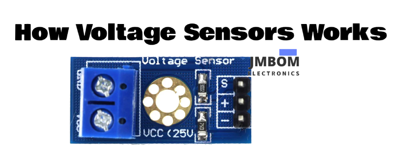
A voltage sensor is a device used to detect, measure, and monitor the level of voltage in a system. It can sense both AC (alternating current) and DC (direct current) voltages. The input to the sensor is the voltage to be measured, while the output can vary depending on the application—it might be a switch signal, an analog voltage, a current output, or even an audible alert.
Some voltage sensors produce output in the form of sine or pulse waveforms, while others generate signals such as AM (Amplitude Modulation), PWM (Pulse Width Modulation), or FM (Frequency Modulation). In many cases, the sensing principle relies on a voltage divider circuit to scale the voltage down to a measurable level.
Voltage Sensor Input and Output Configuration
A voltage sensor typically consists of input and output terminals. The input side usually has two pins—positive and negative—which are connected to the corresponding terminals of the voltage source being measured. The device's positive and negative terminals should match the sensor’s input pins to ensure proper functionality.
On the output side, the sensor generally provides three connections: supply voltage (Vcc), ground (GND), and an analog output signal that represents the measured voltage level.
Types of Voltage Sensors
Voltage sensors are generally categorized into two main types: resistive and capacitive sensors.
Resistive Voltage Sensor
This type of sensor primarily relies on two basic circuit configurations—a voltage divider and a bridge circuit. In these setups, resistors serve as the sensing elements. A typical voltage divider is formed using a fixed reference resistor and a variable resistor. When a voltage source is applied, the output voltage is determined by the ratio of the resistances. As the resistance changes in response to the input voltage, the output voltage changes accordingly. This variation can then be amplified for further processing or measurement.
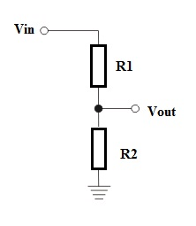
resistive-type-voltage-sensor
The bridge circuit typically consists of four resistors arranged in a specific configuration. One of these resistors is connected to the voltage-sensing element. Any change in voltage affects this resistor, causing an imbalance in the bridge, which directly reflects the voltage variation. This voltage difference can be isolated and amplified.
Unlike a basic voltage divider—where both the reference and sensing resistors influence the output and require additional calibration—the bridge circuit allows the voltage change to be measured more precisely by focusing on the differential output.
Vout = (R1/R1 + R2) * Vin
Capacitive Voltage Sensor
This type of sensor is composed of two conductive plates separated by an insulating material (dielectric). When a 5V supply is applied across the capacitor, an electric field is generated, causing electron displacement between the plates. This results in a current flow and a buildup of charge within the capacitor.
The change in capacitance corresponds to the variation in voltage. In many applications, capacitors are connected in series to enhance sensitivity or adapt to specific voltage ranges. By monitoring the capacitance variation, the sensor can effectively measure the applied voltage.
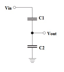
Vout = (C1/C1 + C2) * Vin
Applications of Voltage Sensors
Voltage sensors are widely used in various electrical and electronic systems. Common applications include:
- Power failure detection
- Load monitoring
- Safety interlock and switching
- Temperature control systems
- Power demand regulation
- Fault detection in electrical circuits
- Measuring load variations and related temperature changes
In summary, voltage sensors are essential for detecting voltage levels in electrical devices and systems. They help determine the presence and behavior of electrical charge, ensuring safe and efficient operation. The functionality of these sensors is based on either resistive or capacitive sensing principles.
Frequently Ask Questions
What Are Voltage Sensors?
A voltage sensor is a device used to detect and measure electrical voltage. These sensors can handle a wide range of voltages—from high-voltage applications to detecting low-level signals. They are crucial in many fields, including industrial automation, energy monitoring, and power distribution systems.
How Does a Voltage Sensor Work?
Non-contact voltage sensors typically operate using electrostatic induction. When the sensor is placed near an energized object (like a power outlet), it forms a capacitive link with the target. The electric field generated by the voltage induces a measurable signal in the sensor, allowing it to detect the presence of voltage without direct contact.
What’s the Difference Between a Voltage Sensor and a Current Sensor?
Voltage sensors measure potential difference and are usually connected in parallel with the circuit. In contrast, current sensors must be connected in series so that the current flows through the sensor itself. To avoid affecting circuit behavior, current sensors (like ammeters) are designed with very low internal resistance.
What Are the Signs of a Faulty Battery Voltage Sensor?
Common symptoms of a malfunctioning battery voltage sensor include dashboard warning lights, such as the Battery Warning Light or the Check Engine Light (Malfunction Indicator Lamp). These indicators usually point to issues in the charging or electrical management system of the vehicle.
How Can You Build a Simple Voltage Sensor?
A basic voltage sensor can be built using a voltage divider circuit. For example, if R1 = 30kΩ and R2 = 7.5kΩ, the sensor will output a scaled-down version of the input voltage across R2. This output can then be fed to an ADC (Analog-to-Digital Converter) or microcontroller for monitoring.
Which Sensor Type Produces a Voltage Signal?
Hall effect sensors are a common type of sensor that generate voltage. They work by producing a voltage perpendicular to the direction of current flow when exposed to a magnetic field. These are widely used in current transducers and position sensors.
Does a Voltage Sensor Carry a Positive Charge?
Some biological models of voltage sensing, like the Sliding Helix or Helical Screw model, describe how positively charged amino acids in voltage-sensing domains (such as the S4 segment in ion channels) move in response to voltage changes. In general electronic sensors, however, "charge" is not a characteristic of the sensor itself, but rather what it measures.
How Do You Check the Output Voltage of a Sensor?
If the sensor’s output is a current signal (e.g., 4–20 mA), you can measure the voltage across a known resistor (commonly 250Ω) placed in series. The resulting voltage drop can be used to calculate whether the sensor is functioning properly.
Do Sensors Work with AC or DC Power?
Sensors are available for both AC and DC systems. Depending on the type, they can provide analog outputs (like voltage or current) or digital signals. The choice depends on the application and the type of electrical signal being monitored.
What Is a Sensor That Detects Electrical Activity?
Electrical sensors are specialized devices that detect and measure parameters such as voltage and current. They provide essential data for system monitoring, diagnostics, and control—playing a vital role in ensuring safe and efficient operation in a wide range of industries.
Related Articles
Logic Analyzers: Overview, Function, Types, Comparison & Maintenance
Passive High-Pass Filter: Overview, Circuit Design, Operation & Types
ESP32-S3 vs ESP32: What’s the Difference?
Chemical Sensors: Design, Operation, Types and Comparison with Biosensors
ESP32 vs Arduino: What’s the Difference?
Designing a Voltage Regulator Using a MOSFET
Thin Film Transistor: Structure, Working, Connection & Applications

Christopher Anderson
Christopher Anderson has a Ph.D. in electrical engineering, focusing on power electronics. He’s been a Senior member of the IEEE Power Electronics Society since 2021. Right now, he works with the KPR Institute of Engineering and Technology in the U.S. He also writes detailed, top-notch articles about power electronics for business-to-business electronics platforms.
Subscribe to JMBom Electronics !


