


Passive High-Pass Filter: Overview, Circuit Design, Operation & Types
Catalog
What Is a Passive High-Pass Filter?Passive High-Pass Filter CircuitPassive High-Pass Filter Transfer FunctionTypes of Passive High-Pass FiltersFirst-Order Passive High-Pass FilterSecond-Order Passive High-Pass FilterApplications of Passive High-Pass FiltersFrequently Ask QuestionsRelated ArticlesA high-pass filter is an electronic circuit designed to allow signals with frequencies higher than a specific cutoff frequency to pass through while reducing the amplitude of signals with lower frequencies. It performs the opposite function of a low-pass filter and is commonly referred to as an HPF, bass-cut filter, or low-cut filter.
When a high-pass filter is combined with a low-pass filter, the result is a band-pass filter, which permits only signals within a certain frequency range. High-pass filters come in various types depending on their circuit design and the components used. These include active high-pass filters, passive HPFs, RC high-pass filters, first-order and second-order HPFs, as well as Butterworth, Chebyshev, and Bessel configurations.
This article provides a clear introduction to passive high-pass filters, including their circuit structure, how they work, the different types available, and their typical applications.

What Is a Passive High-Pass Filter?
A passive high-pass filter is an electronic circuit that allows high-frequency signals to pass through while blocking or reducing low-frequency signals. It's called “passive” because it operates without any external power source and relies solely on the energy of the input signal.
This type of filter is built using only passive components such as resistors, capacitors, and inductors. The cutoff frequency—the point where lower frequencies begin to be attenuated—is determined by the specific values of these components.
Passive High-Pass Filter Circuit
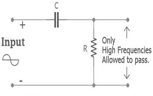
The basic passive high-pass filter circuit is made using a resistor and a capacitor, as shown below. It closely resembles a passive low-pass filter (LPF) circuit, but with the positions of the resistor and capacitor swapped. In this configuration, the capacitor is connected in series with the input signal, followed by the resistor.
When an AC signal is applied to this series combination of a non-polarized capacitor and resistor, the output is typically taken across the resistor. This setup allows high-frequency signals to pass through while attenuating lower frequencies.
The cutoff frequency of the filter depends on the values of the resistor and capacitor used. These passive high-pass filters are often used in high-frequency applications, typically around 10 MHz. Due to the reversed positions of the components compared to a low-pass filter, the behavior of the capacitor in this circuit is essentially the opposite, resulting in a high-pass response instead of a low-pass one.
Passive High Pass Filter
At low frequencies, the capacitor in this circuit behaves like an open circuit, effectively blocking the signal. At higher frequencies, it acts more like a short circuit, allowing the signal to pass through. This behavior is due to the capacitor's capacitive reactance, which is inversely proportional to frequency. As the frequency increases, the reactance decreases, allowing higher-frequency signals to pass while blocking lower-frequency ones.
In this circuit, the capacitor resists a certain amount of current depending on its capacitance. However, once the input signal exceeds the cutoff frequency, the capacitor’s reactance decreases significantly, allowing more of the signal to pass through. This is why the filter effectively passes the entire input signal to the output when the signal frequency is higher than the cutoff frequency, denoted as fc.
At lower frequencies, the capacitive reactance is much higher, which increases the capacitor’s resistance to current flow and blocks those signals. The range of frequencies below the cutoff frequency is known as the Stop Band, while the range above the cutoff frequency is referred to as the Pass Band.
Cut-off Frequency
The cut-off frequency (fc) of a passive high-pass filter can be calculated using the following formula, which is similar to that of a low-pass filter:fc=12πRCf_c = \frac{1}{2\pi RC}fc=2πRC1
Here:
- R is the resistance (in ohms)
- C is the capacitance (in farads)
At this frequency, the output signal drops to 70.7% of the input signal (i.e., -3 dB point), marking the boundary between the stop band and the pass band.
Phase Angle of a Passive High-Pass Filter
The phase angle (φ) of a passive high-pass filter indicates how much the output signal leads the input signal in phase. At the cut-off frequency, the phase shift is +45°.
Unlike a low-pass filter, which introduces a negative phase shift (lag), a high-pass filter introduces a positive phase shift (lead). The phase shift increases with frequency and approaches +90° at very high frequencies.
The formula for calculating the phase shift is:ϕ=arctan(12πfRC)\phi = \arctan\left(\frac{1}{2\pi fRC}\right)ϕ=arctan(2πfRC1)
Where:
- f is the input signal frequency
- R and C are the resistance and capacitance values in the circuit
Time Constant (τ) in a Passive High-Pass Filter
In a passive high-pass filter, the time constant (denoted by the Greek letter τ, or "tau") represents the time it takes for the capacitor to charge or discharge in response to the input signal. It plays a crucial role in determining how the filter reacts to changes in frequency and is directly related to the cutoff frequency.
The time constant is given by the formula:τ=RC=12πfc\tau = RC = \frac{1}{2\pi f_c}τ=RC=2πfc1
Where:
- τ is the time constant (in seconds)
- R is the resistance (in ohms)
- C is the capacitance (in farads)
- fc is the cutoff frequency (in Hz)
If the time constant is known, the cutoff frequency can be calculated using:fc=12πRC=12πτf_c = \frac{1}{2\pi RC} = \frac{1}{2\pi \tau}fc=2πRC1=2πτ1
Example: Calculating the Cut-off Frequency
Let’s calculate the cutoff frequency of a passive high-pass filter using a 330kΩ resistor and a 100pF capacitor.
Given:
- R=330,000 ΩR = 330,000 \, \OmegaR=330,000Ω
- C=100 pF=100×10−12 FC = 100 \, \text{pF} = 100 \times 10^{-12} \, \text{F}C=100pF=100×10−12F
Cutoff frequency formula:fc=12πRCf_c = \frac{1}{2\pi RC}fc=2πRC1
Substitute the values:fc=12×3.14×330000×100×10−12f_c = \frac{1}{2 \times 3.14 \times 330000 \times 100 \times 10^{-12}}fc=2×3.14×330000×100×10−121fc≈4825 Hz or 4.825 kHzf_c ≈ 4825 \, \text{Hz} \, \text{or} \, 4.825 \, \text{kHz}fc≈4825Hzor4.825kHz
So, the filter will start allowing signals above approximately 4.825 kHz to pass through.
Passive High-Pass Filter Transfer Function
The transfer function of a passive high-pass filter describes the relationship between the output voltage (Vo) and the input voltage (Vin) as a function of frequency. It helps determine how the filter responds to different frequency signals.
Passive HPF Transfer Function
Derivation:
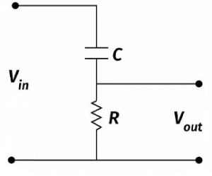
Consider a simple RC high-pass filter where the input voltage (Vin) is applied across a series combination of a capacitor (C) and a resistor (R), and the output voltage (Vo) is taken across the resistor.
From Ohm’s Law and impedance in the frequency domain:Vin=I⋅Z=I(R+1jωC)V_{in} = I \cdot Z = I \left(R + \frac{1}{j\omega C} \right)Vin=I⋅Z=I(R+jωC1)Vo=I⋅RV_o = I \cdot RVo=I⋅R
So, the transfer function H(jω) is:VoVin=IRI(R+1jωC)=RR+1jωC=jωRC1+jωRC\frac{V_o}{V_{in}} = \frac{IR}{I \left(R + \frac{1}{j\omega C} \right)} = \frac{R}{R + \frac{1}{j\omega C}} = \frac{j\omega RC}{1 + j\omega RC}VinVo=I(R+jωC1)IR=R+jωC1R=1+jωRCjωRC
Let’s define the cutoff angular frequency as:ωc=1RC\omega_c = \frac{1}{RC}ωc=RC1
So, the normalized form of the transfer function becomes:VoVin=j(ω/ωc)1+j(ω/ωc)\frac{V_o}{V_{in}} = \frac{j(\omega / \omega_c)}{1 + j(\omega / \omega_c)}VinVo=1+j(ω/ωc)j(ω/ωc)
This equation gives the voltage gain as a function of frequency. It shows that:
- At very low frequencies (ω≪ωc\omega \ll \omega_cω≪ωc), the gain approaches 0.
- At the cutoff frequency (ω=ωc\omega = \omega_cω=ωc), the gain is 12≈0.707\frac{1}{\sqrt{2}} \approx 0.70721≈0.707 (or -3 dB).
- At high frequencies (ω≫ωc\omega \gg \omega_cω≫ωc), the gain approaches 1 (or 0 dB).
Types of Passive High-Pass Filters
Passive high-pass filters are mainly categorized into two types based on their order:
- First-Order Passive High-Pass Filter
- Second-Order Passive High-Pass Filter
First-Order Passive High-Pass Filter
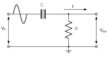
A first-order passive high-pass filter consists of just one reactive component (a capacitor) and one resistor. The circuit is simple and does not require an external power supply, making it a passive filter.
In this configuration, the capacitor is connected in series with the resistor, and the output is taken across the resistor. The filter blocks low-frequency signals and allows high-frequency signals to pass once the frequency exceeds the cutoff point.
This basic RC circuit is often used in audio equipment, signal conditioning, and communication systems where simple frequency filtering is needed.
First Order Passive High Pass Filter Circuit
Cut-off Frequency for First-Order Passive High-Pass Filter
The cutoff frequency (fc) formula for a first-order passive high-pass filter is the same as that for a passive low-pass filter:fc=12πRCf_c = \frac{1}{2\pi RC}fc=2πRC1
Where:
- R is the resistance
- C is the capacitance
Second-Order Passive High-Pass Filter
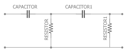
A second-order passive high-pass filter is created by cascading two first-order high-pass filters. This means the circuit uses two resistors and two capacitors, making it a second-order system.
Although it consists of two stages, the overall performance is similar to a single filter, but with a steeper slope. Specifically, the roll-off rate of this filter is -40 dB per decade, which is twice as steep as the -20 dB per decade slope of a first-order filter. This results in better attenuation of frequencies below the cutoff frequency.
Second Order Passive High Pass Filter
Efficiency and Cut-off Frequency of Second-Order Passive High-Pass Filters
The second-order passive high-pass filter is more effective than a single-stage filter because it has two energy storage elements (capacitors), which improve its filtering performance. The cutoff frequency for this two-stage filter depends on the values of both resistors and capacitors and is calculated as:fc=12πR1C1R2C2Hzf_c = \frac{1}{2\pi \sqrt{R_1 C_1 R_2 C_2}} \quad \text{Hz}fc=2πR1C1R2C21Hz
Where:
- R1,R2R_1, R_2R1,R2 are the resistor values
- C1,C2C_1, C_2C1,C2 are the capacitor values
Applications of Passive High-Pass Filters
Passive high-pass filters are widely used in many fields due to their ability to block low-frequency signals while allowing high-frequency signals to pass above a set threshold. Common applications include:
- Audio systems: Used in equalizers and audio receivers to filter out unwanted low-frequency noise.
- Music control and frequency modulation: Help in shaping and controlling sound signals.
- Signal generators: Employed in function generators, pulse generators, ramp-to-step generators, and oscilloscopes (CROs, CRTs).
- Audio processing: Remove low-frequency hum or noise from audio amplifiers, ensuring clarity in the higher-frequency range.
- Image processing: Enhance edges and other high-frequency details in digital images by filtering out lower frequencies.
- Industrial and scientific fields: Used in seismic data analysis, radar systems, and biomedical applications such as ECG signal processing.
Passive high-pass filters are essential components in electronics and signal processing, providing a reliable way to isolate and pass high-frequency signals while attenuating low-frequency interference.
In summary, this is an overview of passive high-pass filters, including their circuits, operation, types, and applications. These filters are built using only passive components like resistors and capacitors. Because they don’t require any external power source, passive filters have no gain—meaning the output signal’s amplitude is always equal to or less than the input signal’s amplitude. Their simple design and low-cost components make them a popular choice in many electronic applications.
Now, here’s a question for you: What is a passive low-pass filter?
Frequently Ask Questions
What Is a Passive Band-Pass Filter?
A passive band-pass filter is typically a second-order filter made by combining two reactive components—usually capacitors and resistors. It’s formed by cascading two first-order RC filter circuits: one high-pass and one low-pass. This design allows the filter to pass frequencies within a specific range while blocking frequencies outside that range.
Types of High-Pass Filters
High-pass filters (sometimes called damped filters) come in several varieties based on their order and complexity:
- First-order: Simple RC circuit with a -20 dB/decade slope
- Second-order: Cascaded first-order filters, -40 dB/decade slope
- Third-order: More complex with steeper roll-off, -60 dB/decade slope
- C-type: Specialized designs often used in RF circuits
Does a High-Pass Filter Remove Bass?
Yes! High-pass filters remove low-frequency signals (bass) that are unnecessary or unwanted in a mix, helping improve clarity. By eliminating low-end buildup, they allow bass-heavy instruments to stand out more distinctly.
Disadvantages of Passive Filters
- They can have limited or less ideal frequency response.
- Physical size can be large, especially if inductors are involved.
- Gain is always 1 or less (no amplification).
- Bulky when inductors are used, which can limit their application in compact devices.
How to Tell If a Filter Is Active or Passive?
- Passive filters use only resistors, capacitors, and inductors. They don’t need a power source.
- Active filters include operational amplifiers (op-amps) plus passive components and require an external power supply to operate.
Difference Between High-Pass and Band-Pass Filters
- High-pass filters block low frequencies and allow high frequencies to pass.
- Low-pass filters block high frequencies and allow low frequencies to pass.
- Band-pass filters allow a specific range (band) of frequencies to pass while blocking frequencies outside that range.
Should I Use a Low-Pass Filter on Vocals?
Using a low-pass filter on vocals can help reduce unwanted high frequencies, making space in the mix for other instruments and preventing clutter. It’s especially useful if you want a cleaner, less muddy sound.
What Frequencies Does a High-Pass Filter Remove?
High-pass filters remove low-frequency noise and allow high-frequency signals to pass through. Conversely, low-pass filters remove high-frequency noise and smooth out the signal. Band-pass filters allow only a specific frequency range to pass.
Related Articles
ADXL335 Accelerometer Module: Pin Configuration, Features & Internal Components
Preamplifiers: What They Are, How They Work, Types and Differences
Metal Oxide Film Resistors: Structure, Operation and Key Specs
Semiconductor Fuse: Structure, HSN Code, Operation, and Common Uses
DC Servo Motor: Structure, Operation, Arduino Interface & Common Uses
Iron Core Inductor : Construction, Formula, Working & Its Applications
Air Core Inductors: Design, Operation, Inductance, and Common Uses
Logic Analyzers: Overview, Function, Types, Comparison & Maintenance

Christopher Anderson
Christopher Anderson has a Ph.D. in electrical engineering, focusing on power electronics. He’s been a Senior member of the IEEE Power Electronics Society since 2021. Right now, he works with the KPR Institute of Engineering and Technology in the U.S. He also writes detailed, top-notch articles about power electronics for business-to-business electronics platforms.
Subscribe to JMBom Electronics !


