


Logic Analyzers: Overview, Function, Types, Comparison & Maintenance
Catalog
What Is a Logic Analyzer?Logic Analyzer Block DiagramHow Does a Logic Analyzer Work?Steps Involved in Using a Logic AnalyzerTypes of Logic AnalyzersLogic Analyzer vs OscilloscopeMaintenance of Logic AnalyzersAdvantages and DisadvantagesApplications of Logic AnalyzersLogic Analyzer – Frequently Asked QuestionsRelated ArticlesIn modern digital systems, the ability to monitor and analyze multiple digital signals at once is crucial for identifying design issues and solving operational faults. Logic analyzers were introduced alongside the early development of microprocessors to address these needs. Engineers quickly realized that these tools were highly effective for troubleshooting the complex behavior of digital circuits in microprocessor-based systems.
Today, logic analyzers remain an essential part of the toolkit for engineers working on digital circuit design. They are widely used for verifying system designs, debugging embedded software, and troubleshooting digital hardware.
This article provides a comprehensive overview of logic analyzers, including how they work, their various types, key differences, maintenance tips, and typical applications.
What Is a Logic Analyzer?
A logic analyzer is a powerful diagnostic instrument used to capture and display multiple digital signals from a circuit or system. Much like other electronic test tools, it helps engineers monitor the behavior of digital devices. The analyzer converts the captured data into readable formats such as timing diagrams, state machine traces, or decoded communication protocols. In some cases, it can even link machine-level operations (opcodes) to the original source code.
Logic analyzers are equipped with advanced triggering features that make it easier to examine how different signals interact over time. This makes them especially useful for identifying timing issues between digital signals.
Some models are capable of detecting glitches, as well as setup and hold violations, which helps troubleshoot hard-to-find, intermittent problems. In hardware-software integration, logic analyzers allow engineers to trace embedded software execution and evaluate its real-time performance. They can also help correlate specific software instructions with hardware activity to better understand system behavior.
Logic Analyzer Block Diagram
Below is a basic block diagram illustrating the main functional components of a logic analyzer.
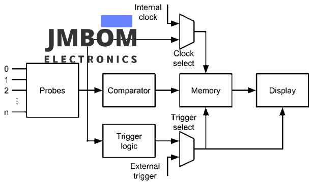
Logic Analyzer Block Diagram
Probes
Probes are the physical connectors used to link a logic analyzer to the digital circuit being tested. These are often simple components—such as small circuits or wire clips—that allow the analyzer to capture and interpret digital signals from the system under test.
Logic analyzer probes come in various types, including test points, specialized connectors, and flying lead probes. Each type offers specific features suited to different testing scenarios. Choosing the right probe and setting it up correctly is critical for ensuring accurate signal capture and reliable troubleshooting of digital systems.
Clock Select
Some logic analyzers offer a feature called "Clock Select," which allows you to choose the clock source used during signal analysis. You can either use the analyzer’s internal clock to sample signals at fixed intervals or assign one of the input channels as an external clock source. This flexibility helps match the timing of signal capture to the behavior of the circuit being tested.
Comparator
Unlike oscilloscopes, logic analyzers evaluate each input signal against a user-defined voltage threshold. If a signal’s voltage exceeds the threshold, it is recorded as a logic high; otherwise, it is recorded as a logic low. Since logic analyzers work with digital signals rather than analog waveforms, they do not require analog-to-digital converters (ADCs). They also typically support a larger number of input channels than oscilloscopes.
Trigger Logic
Logic analyzers generally offer more advanced triggering capabilities compared to oscilloscopes. Any of the active channels can be used to initiate a signal capture. High-end models even support complex trigger configurations using conditional logic, such as if-then-else statements, to precisely isolate specific events or faults.
Trigger Select
Some logic analyzers let you select the source of the trigger—either from a dedicated trigger input or from one of the data capture channels. This flexibility allows you to synchronize the logic analyzer with other test equipment, such as oscilloscopes, for more coordinated measurements.
Memory
Logic analyzers include built-in memory that stores the sequence of captured digital signals—represented as logic 0s and 1s. This stored data allows for detailed analysis of the circuit’s behavior over time.
Display
The captured digital signals are typically shown as waveforms on a display screen. Similar to an oscilloscope, the X-axis represents time. However, instead of showing continuous voltage levels, logic analyzers use voltage thresholds to determine logic states. If the voltage is above the threshold, it’s displayed as a logic high; if it’s below, it’s shown as a logic low.
How Does a Logic Analyzer Work?
A logic analyzer functions by sampling multiple digital signals at regular intervals and converting the voltage levels into logic values—0s and 1s. It then uses this data to visualize the timing and behavior of signals within a digital circuit. Engineers use this information to analyze timing relationships, debug faults, and validate the overall operation of digital systems.
Steps Involved in Using a Logic Analyzer
1. Signal Capture
The logic analyzer connects to different test points in the circuit using probes. These probes are specifically designed to detect logic high and low levels in digital signals. The analyzer samples the signals at regular, user-defined intervals—essentially taking snapshots of the voltage levels over time to track signal transitions.
2. Data Acquisition & Storage
The sampled signals are converted into binary data and stored in the logic analyzer’s internal memory. The depth of this memory determines how much data can be captured in a single session. Many logic analyzers also feature configurable triggering options, allowing users to define specific conditions that must be met before data acquisition begins.
3. Display & Analysis
Once data is captured, it is typically displayed on the screen in the form of timing diagrams. These diagrams provide a visual representation of signal transitions over time, making it easier to spot timing issues, glitches, or signal anomalies. Advanced logic analyzers can also decode digital protocols (such as I2C, SPI, or UART), presenting them in a human-readable format for easier analysis and debugging.
Specifications
Key specifications of a logic analyzer typically include the following:
- Channel Count: Logic analyzers are available with a range of input channels, from just a few to over a hundred, allowing simultaneous monitoring of multiple signals.
- Timing Mode: In this mode, the analyzer samples signals at very high speeds—useful for analyzing timing relationships between signals and detecting glitches.
- State Mode: This mode captures logic states in sync with a defined clock edge, making it ideal for examining data transfers and evaluating protocol behavior.
- Timing Speed: Expressed in bandwidth terms (e.g., 12.5 GHz), this indicates how quickly the analyzer can detect signal transitions.
- State Data Rate: Specifies the maximum rate (e.g., 4 Gb/s) at which synchronized data can be captured with respect to an external clock signal.
- Memory Depth: Defines how much data the analyzer can store during capture—ranging from 2 MB in standard mode to up to 256 MB in half-channel configurations.
- Triggering Capabilities: Logic analyzers support advanced triggering options, including user-defined sequences or specific events for capturing complex signal interactions.
- Protocol Support: Many analyzers can decode and interpret common digital communication protocols such as I²C, SPI, DDR, and USB.
- Display Quality: High-resolution displays are used to clearly present timing diagrams and decoded protocol data for easier signal analysis.
- Probes and Signal Integrity: The quality and type of probes used can significantly impact measurement accuracy and overall signal integrity.
- Software Features: Integrated software often includes features such as packet viewers, protocol analysis tools, and real-time decoding for efficient debugging and review.
Types of Logic Analyzers
Logic analyzers are generally available in three main types: modular, portable, and PC-based. Each type serves different needs based on performance, flexibility, and portability.
Modular Logic Analyzer
Modular logic analyzers are high-end instruments typically found in professional labs and advanced testing environments. These systems consist of a mainframe chassis that houses multiple plug-in modules. Each module supports a specific number of channels and offers specialized functionality, such as protocol decoding or deep memory capture.
Modular analyzers are designed for analyzing complex digital systems and offer maximum flexibility. Users can expand the system by adding or removing modules based on their testing needs.
- Advantages: Exceptional performance and signal analysis capabilities Support for a large number of channels Advanced triggering and protocol decoding features
- Disadvantages: High cost Bulky and less portable
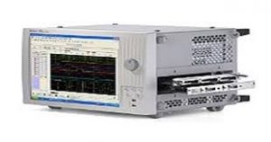
Modular Logic Analyzer
Portable Logic Analyzer
A portable logic analyzer is a compact, self-contained electronic test instrument designed to capture and analyze digital signals in circuits or systems. These units typically include a built-in display and control interface, making them ideal for on-site troubleshooting, field diagnostics, and embedded system debugging.
Portable analyzers usually support essential features such as timing and state analysis, along with basic triggering capabilities. While they offer ease of use and mobility, they are generally more limited in terms of channel count and advanced functions compared to modular systems.
- Advantages: Lightweight and easy to transport Convenient for field testing and on-site debugging User-friendly interface for quick setup and analysis
- Disadvantages: Lower channel count Fewer advanced features compared to modular analyzers
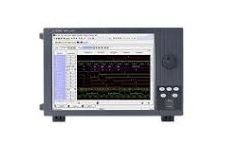
Portable Logic Analyzer
PC-Based Logic Analyzer
A PC-based logic analyzer is a compact device that connects to a computer—usually via USB or Ethernet—and uses the computer’s display, processing power, and storage for capturing and analyzing digital signals. Unlike standalone analyzers, it relies entirely on the connected PC for its user interface and data processing, eliminating the need for a dedicated display or processor in the analyzer itself.
- Advantages: Most affordable option Extremely compact and highly portable Leverages the power and flexibility of the PC
- Disadvantages: Limited advanced features compared to modular or portable analyzers Performance constraints depending on the PC’s capabilities
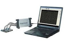
PC-based
Logic Analyzer vs Oscilloscope
| Feature | Logic Analyzer | Oscilloscope |
|---|---|---|
| Bandwidth | Moderate, optimized for digital signals | High, suitable for both high and low frequency signals |
| Memory Depth | Large, ideal for capturing long digital sequences | Variable, generally less than logic analyzers |
| Channels | Many digital channels | Fewer analog and digital channels |
| Sample Rate | Moderate, enough for digital signal analysis | High, necessary to capture fast analog waveforms |
| Triggering | Designed for digital signal events | Primarily optimized for analog signals |
| Portability | Available in compact models | Available in portable models |
| Cost | Generally lower cost | Typically more expensive |
Logic Analyzer vs Spectrum Analyzer
| Feature | Logic Analyzer | Spectrum Analyzer |
|---|---|---|
| Primary Use | Used by engineers to analyze and debug digital circuits and systems, focusing on logic states and signal timing | Used by technicians to measure signal power across frequencies, mainly in RF and microwave ranges |
| Signal Type | Digital signals, logic states, and timing relationships | Analog signals, often in audio, RF, or microwave frequencies |
| Functionality | Captures multiple digital signals simultaneously, provides timing diagrams, and supports protocol decoding | Measures signal power across frequency ranges, detects spurious signals, and analyzes modulation characteristics |
| Input Channels | Multiple digital input channels | Typically single or few analog input channels |
| Data Display | State diagrams, protocol decodes, timing diagrams | Amplitude vs frequency plots showing noise, frequency response, and distortion |
| Typical Applications | Debugging digital interfaces like SPI buses or microcontroller-memory interactions | Measuring Wi-Fi signal strength, identifying interference in cellular networks, troubleshooting RF amplifiers |
| Output Visualization | Timing diagrams | Frequency spectrum plots |
Maintenance of Logic Analyzers
Proper maintenance is essential to ensure accurate and reliable operation of a logic analyzer. Key maintenance steps include:
- Cleaning Keep the logic analyzer and its probes free from dust, dirt, and debris. Avoid using harsh chemicals or solvents that could damage sensitive components.
- Storage Store the device in a cool, dry place away from direct sunlight and extreme temperatures. Use a protective case or the original packaging to prevent physical damage during storage.
- Grounding and Probe Care Ensure proper grounding by connecting the shortest possible ground path for every two signals when using flying lead probes. Maintain probe cables carefully to minimize signal reflections and preserve signal integrity. Use the appropriate type of probe for your application; for example, low-capacitance probes are recommended for high-speed digital systems.
- Calibration Many logic analyzers include self-calibration features that should be run periodically. After calibration, verify the analyzer’s accuracy using calibration standards or known test signals.
- Software Maintenance Keep the logic analyzer’s software updated to take advantage of the latest features and bug fixes. Familiarize yourself with the software’s capabilities to optimize your testing workflow. Choose the appropriate software for your needs, whether it’s the manufacturer’s proprietary tools (e.g., Keysight) or reliable open-source alternatives.
Advantages and Disadvantages
Advantages of Logic Analyzers
- Simultaneous Multi-Signal Measurement Logic analyzers can capture multiple digital signals at the same time and display their relative timing relationships, making it easier to analyze complex interactions.
- High-Speed Signal Capture They are capable of capturing very fast signals, which is essential for debugging high-speed digital circuits.
- Flexible Data Display Formats Captured data can be viewed in various formats such as ASCII, binary, hexadecimal, or decimal, depending on the user’s preference.
- Event-Triggered Capture Logic analyzers can be set to start capturing data only when specific events or patterns occur, allowing targeted debugging.
- Cost-Effective for Embedded Systems Debugging Engineers often find logic analyzers affordable and practical tools for verifying communication between microcontrollers, peripherals, and other embedded components.
- Configurable Sampling and Acquisition Users can adjust sampling rates, acquisition times, and channel counts to suit a wide variety of debugging scenarios.
- Advanced Triggering Capabilities These analyzers offer complex triggering options to capture data based on intricate signal patterns or conditions.
- Protocol Decoding Logic analyzers can decode numerous digital communication protocols, simplifying the process of verifying and troubleshooting data transfers.
- Dual Timing and State Analysis Modes Many models support both timing and state analysis, providing comprehensive insights into signal behavior.
- Integration with Oscilloscopes Some logic analyzers can be combined with oscilloscopes, enabling time-correlated and cross-triggered displays of analog and digital signals simultaneously.
- Signal Integrity Diagnostics They help identify issues such as crosstalk, signal reflections, and other signal integrity problems critical to reliable system performance.
Disadvantages of Logic Analyzers
- Cost Logic analyzers can be expensive, especially models with high sampling rates and large numbers of channels.
- Limited Measurement Scope They measure logic levels (high or low) rather than actual current or voltage, which can be a limitation for certain applications that require analog measurements.
- Not Ideal for Analog or Very High-Speed Signals Logic analyzers are primarily designed for digital signals. For analyzing high-speed analog signals, oscilloscopes or specialized instruments are usually more suitable.
- Complex Configuration Setting up a logic analyzer and its software can be challenging, particularly for users unfamiliar with the device.
- Limited Application Scope Their use is mainly restricted to digital circuit analysis, limiting their usefulness in broader electrical testing.
- External Connections Required They often require external probes or wires to connect to the system under test, which can be cumbersome.
- Separate Hardware for State and Timing Capture Some models need additional hardware or probes to capture both state and timing data, which can complicate the setup and analysis process.
- Potential for Noise Introduction Depending on the hardware and signal environment, noise may be introduced during measurement, affecting signal integrity.
- Memory Limitations Despite capturing large amounts of data, some logic analyzers have limited memory, which can restrict long-duration captures or high-speed signal analysis.
Applications of Logic Analyzers
- Logic analyzers are essential instruments for analyzing and capturing digital signals, primarily used to verify and debug digital circuits and systems.
- They can simultaneously capture multiple signals, trace their relative timing relationships, and display data in various formats.
- In embedded systems, logic analyzers play a critical role in verifying and debugging by allowing designers to examine timing relationships, overall system performance, and protocol behavior.
- They are valuable for identifying protocol errors, examining timing issues, and troubleshooting digital hardware.
- Logic analyzers provide powerful insights that help designers diagnose and fix problems at the hardware level.
- Their flexibility makes them widely applicable across embedded system development and digital design projects.
A logic analyzer is a crucial tool for analyzing and debugging digital systems, capable of capturing and displaying multiple digital signals simultaneously. It is especially valuable in protocol analysis, digital circuit design, and embedded system development. Additionally, it can generate timing diagrams, state machine traces, and protocol decodes, making it indispensable for identifying and solving complex problems.
Logic Analyzer – Frequently Asked Questions
What is the difference between a logic analyzer and an oscilloscope?
An oscilloscope is best suited for observing analog signal waveforms. It typically offers higher sample rates, which are essential for capturing fast, transient signal details like voltage spikes, ripple, or waveform distortion.
A logic analyzer, on the other hand, is optimized for digital systems. It focuses on capturing state changes (highs and lows) across multiple digital channels simultaneously. While it generally has a lower sample rate, it's ideal for debugging digital protocols, timing relationships, and logic-level activity.
How do I choose the right logic analyzer?
Key factors to consider include:
- Trigger Capabilities: Look for an analyzer with advanced and flexible triggering, such as nested conditions, pattern matching, and protocol-specific triggers.
- Probe Type: Probes should connect easily and cleanly to your circuit. Low-capacitance and high-impedance probes help maintain signal integrity, especially in high-speed systems.
- Channel Count & Memory Depth: Ensure the analyzer has enough channels to monitor all relevant signals, and sufficient memory to store long captures.
Does a logic analyzer require grounding?
Yes, proper grounding is essential for accurate data capture. It is recommended to connect at least one ground wire for every two signal wires. Poor grounding can lead to noise, incorrect readings, or failure to capture data properly.
How does a logic analyzer work?
A logic analyzer samples digital signals from multiple channels at regular intervals and stores the data in internal memory (a buffer). The data is then displayed as timing diagrams, protocol decodes, or logic states. Some advanced logic analyzers can display signals in real-time, similar to an oscilloscope.
What are the advantages of a logic analyzer?
- Captures high-speed digital signals that may be missed by other instruments
- Displays data in multiple formats: binary, ASCII, decimal, and hexadecimal
- Powerful triggering options, including edge detection, pulse width, or protocol-based triggers
- Supports multiple channels, ideal for monitoring complex digital systems
- Decodes standard communication protocols (e.g., I²C, SPI, UART, USB)
What are the applications of a logic analyzer?
- Dynamic Timing Analysis: Monitor how signals behave under real-time operational conditions to detect glitches or timing violations.
- Protocol Debugging: Decode and analyze data from digital communication interfaces.
- Embedded System Development: Verify correct interaction between microcontrollers, memory, sensors, and peripherals.
- Hardware Debugging: Identify crosstalk, signal integrity problems, or invalid logic states.
Related Articles
ESP32-S2 Development Board: Pinout, Features & Specs
ADXL335 Accelerometer Module: Pin Configuration, Features & Internal Components
Preamplifiers: What They Are, How They Work, Types and Differences
Metal Oxide Film Resistors: Structure, Operation and Key Specs
Semiconductor Fuse: Structure, HSN Code, Operation, and Common Uses
DC Servo Motor: Structure, Operation, Arduino Interface & Common Uses
Iron Core Inductor : Construction, Formula, Working & Its Applications
Air Core Inductors: Design, Operation, Inductance, and Common Uses

Christopher Anderson
Christopher Anderson has a Ph.D. in electrical engineering, focusing on power electronics. He’s been a Senior member of the IEEE Power Electronics Society since 2021. Right now, he works with the KPR Institute of Engineering and Technology in the U.S. He also writes detailed, top-notch articles about power electronics for business-to-business electronics platforms.
Subscribe to JMBom Electronics !


