


Automatic Transfer Switch (ATS): Working Principle & Applications
Catalog
What is an Automatic Transfer Switch?Automatic Transfer Switch Working PrincipleAutomatic Transfer Switch Circuit DiagramWorkingTypes of Automatic Transfer SwitchesHow an Automatic Transfer Switch Detects a Power LossAutomatic Transfer Switch vs. Static Transfer SwitchHow an Automatic Transfer Switch Detects a Power LossAutomatic Transfer Switch vs. Static Transfer SwitchAdvantages and DisadvantagesApplicationsHow Much Does an Automatic Transfer Switch (ATS) Cost?Related ArticlesA transfer switch is designed to switch an electrical load between two power sources—typically a primary (main) supply and a backup supply. These switches enable the safe connection or disconnection of different power sources to an electrical load. It is critical to properly isolate power sources when they are not in use and ensure that transitions from one power supply to another occur in a safe, controlled manner.
Transfer switches are available in two main types: automatic transfer switches and manual transfer switches. Manual switches require operation by a person, whereas automatic transfer switches (ATS) function automatically: they detect when one power source either loses power or is restored, then initiate the switch without human intervention. This article provides an overview of automatic transfer switches (ATS), one of the two primary types of transfer switches.
What is an Automatic Transfer Switch?
An automatic transfer switch, or ATS, is a device that automatically transfers an electrical load from its primary power source to a backup source when it detects a failure or outage in the main supply. When the main power system experiences an outage, the ATS immediately activates a standby power source such as a UPS (uninterruptible power supply). The symbol for an automatic transfer switch is shown below.
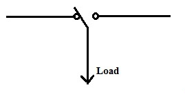
ATS Symbol
Once the automatic transfer switch is connected to both the primary and backup power sources, it functions as an electrical relay, acting as an intermediary between the connected equipment and the power supplies.
Automatic Transfer Switch Working Principle
The operating principle of an automatic transfer switch (ATS) is to automatically switch the electrical load between the primary and backup power sources without any human intervention. As a critical component within an Emergency Power Supply System (EPSS), the ATS ensures uninterrupted power delivery.
These switches incorporate a set of relays and solid-state devices that continuously monitor and regulate the incoming voltage. Acting as a power monitor, the ATS verifies that the supply voltage is stable and maintained above a predefined threshold. If the voltage drops below this level, the solid-state relay detects the anomaly and sends a signal to start the backup generator.
The ATS serves as the central control element for connecting the standby generator to a residential or commercial electrical system. Under normal conditions, electricity flows from the utility grid to the main electrical panel, powering all connected circuits. In this setup, the ATS functions as the "brain" of the system, facilitating automatic switching between utility and generator power. Upon detecting a mains power failure, the ATS immediately redirects power from the generator to the facility. Once utility power is restored and stabilized, the ATS automatically switches the load back to the grid supply.
Automatic Transfer Switch Circuit Diagram
The wiring diagram for a single-phase automatic transfer switch paired with a generator is illustrated below. This configuration is characterized by its simplicity and cost-effectiveness. The primary components required for this wiring setup include one magnetic contactor, two MCBs (Miniature Circuit Breakers), power cables, and control wiring.
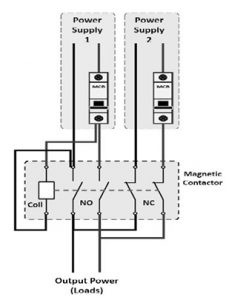
Automatic Transfer Switch Wiring Diagram
Working
When the utility power supply is active, current flows to the contactor and its coil, energizing the unit. This causes the normally open (NO) terminals to close, routing utility power to the residential load, while the normally closed (NC) terminals remain open.
In the event of a utility power failure, the current to the contactor coil is interrupted, de-energizing the contactor. As a result, the NC terminals close and the NO terminals open, restoring the switch to its default state.
When the magnetic contactor is activated, the normally closed (NC) terminals automatically close, allowing power to flow from the generator through the NC terminals to the residential load. In this way, the automatic transfer switch (ATS) seamlessly facilitates the transfer of power—either between the utility supply and the generator, or between generator and utility, as conditions require.
Types of Automatic Transfer Switches
Automatic transfer switches are available in three main types: compact ATS, CB ATS, and contactor ATS. Each type is discussed below.
Compact ATS
The compact automatic transfer switch, also referred to as a changeover switch, is designed to interrupt short-circuit currents. Modern compact ATS models minimize installation time within the panel while delivering a high level of reliability, thanks to their reduced number of interconnecting components. These switches are typically the most expensive option among the three types.
Compact ATS
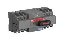
Circuit Breaker ATS
Circuit Breaker (CB) automatic transfer switches are designed for making, breaking, and withstanding short-circuit currents. These switches typically consist of multiple interconnected Air Circuit Breakers (ACBs) or Molded Case Circuit Breakers (MCCBs), assembled with a dedicated controller. All necessary accessories are integrated within the unit.
This type of ATS primarily features two mechanically and/or electrically interlocked circuit breakers, ensuring that only one breaker can be closed at any given time. Compared to contactor-type ATS units, CB ATS are generally more expensive.
Circuit Breaker ATS
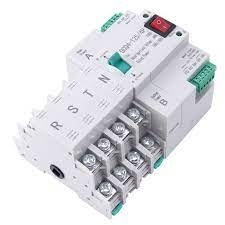
Contactor ATS
Contactor-type automatic transfer switches are designed for making and withstanding short-circuit currents, but they are not intended for breaking short-circuit currents. These units typically rely on 3-pole or 4-pole low-voltage contactors.
Featuring a simple design, contactor ATS units are mechanically interlocked and electrically operated. Compared to circuit breaker-based ATS units, they offer significantly faster operation, resulting in shorter power transfer times. Generally, this type of transfer switch is the most economical option available.
Contactor ATS
How an Automatic Transfer Switch Detects a Power Loss
An automatic transfer switch detects a power loss by continuously monitoring both the incoming and outgoing power lines.
The incoming line is monitored by a voltage sensor, which verifies that the voltage supplied to the system is within a safe, operational range. If the voltage drops below the acceptable threshold, an alarm is triggered, and the ATS initiates the transfer to the standby generator.
The outgoing line is monitored by a frequency sensor, which checks that the system frequency is stable and within safe operating limits. If the frequency falls outside the acceptable range, an alarm is activated, and the ATS begins the switchover to the backup generator.
Automatic Transfer Switch vs. Static Transfer Switch
The key differences between an automatic transfer switch (ATS) and a static transfer switch (STS) are outlined below.
| Automatic Transfer Switch (ATS) | Static Transfer Switch (STS) |
|---|---|
| An intelligent, electromechanical power switching device. | An intelligent, solid-state automatic switching device. |
| Its primary function is to automatically transfer the load from the primary power source to a backup source upon detecting a mains failure. | Its primary function is to transfer critical loads between two independent AC power sources without any interruption to the supply. |
| Typically categorized by its internal mechanism: circuit breaker type or contactor type. | Typically categorized by the phase configuration: single-phase or three-phase. |
| Features a short break (millisecond range) in the power supply during the transfer process. | Provides a break-free power transfer, ensuring no interruption to the load. |
Advantages and Disadvantages
Advantages of Automatic Transfer Switches
- The primary advantage is the automatic transfer of the load from the mains supply to the backup generator during a power outage.
- Equipped with built-in sensors to detect fluctuations in mains voltage and frequency.
- Incorporates a time-delay mechanism to protect both the generator and electrical circuits from power surges or transient fluctuations.
- Highly reliable, simple to operate, and ensures safe power switching.
- Essential for maintaining an uninterrupted power supply to critical systems.
- Ideal for efficient and rapid switching to generator power when needed.
Disadvantages of Automatic Transfer Switches
- The main drawback is a higher potential for operational errors in some installations compared to manual switches.
- Generally more expensive to purchase than manual transfer switches.
- Requires more frequent maintenance than manual switches.
Applications
- Used to protect telecommunications/data networks, industrial processes, and critical facilities such as financial transaction centers and healthcare institutions.
- Facilitates the transfer of electrical power between two sources: typically the primary utility and a secondary backup source.
- Employed in other power-switching scenarios, including utility‑to‑utility, generator‑to‑generator, and three‑source systems.
- Widely installed in hospitals, schools, medical buildings, shopping malls, restaurants, warehouses, factories, and other commercial/residential facilities.
How Much Does an Automatic Transfer Switch (ATS) Cost?
The cost of an ATS varies based on the unit’s size, type, and installation location. For example:
- A small residential ATS can start at around $200.
- A large commercial ATS may exceed $1,000.
- The average price for a typical unit is approximately $500.
This overview covers the working principle and applications of the automatic transfer switch. While its control logic can be complex, the ATS enables fast switching and control between two power sources—often in just a few seconds. It also automatically starts the standby generator when the mains supply fails.
Here’s a question for you: What is a manual transfer switch?
Related Articles
Diode Dynamics: Real-World Behavior in Fast Power and RF Circuits

Christopher Anderson
Christopher Anderson has a Ph.D. in electrical engineering, focusing on power electronics. He’s been a Senior member of the IEEE Power Electronics Society since 2021. Right now, he works with the KPR Institute of Engineering and Technology in the U.S. He also writes detailed, top-notch articles about power electronics for business-to-business electronics platforms.
Subscribe to JMBom Electronics !


