


What Is a DPST Switch? How It Works & Its Applications
Catalog
What Is a DPST Switch?How Does a DPST Switch Work?SpecificationsDPST Switch Circuit DiagramAdvantagesDisadvantagesApplicationsConclusionRelated ArticlesA switch is an electrical component that connects or breaks the conducting path in an electrical circuit. Switches come in various configurations, with multiple sets of contacts operated by the same actuator or knob; these contacts can act sequentially, alternately, or simultaneously. Common types include SPDT, SPST, DPDT, and DPST switches. This article focuses on the DPST switch—explaining how it works and its practical applications.
What Is a DPST Switch?
A DPST switch is a switch that has two inputs and two outputs, with one output corresponding to each input. Each terminal in this type of switch can be independently set to either the ON or OFF position. The symbol for a DPST switch is shown below.
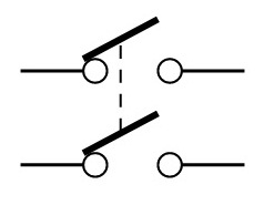
DPST Switch Symbol
n this switch, “DP” stands for Double Pole and “ST” stands for Single Throw.
The term pole refers to how many separate circuits the switch controls, while throw describes the number of active positions for the actuator.
Double-pole switches control two independent circuits at once.
Single-throw switches only close a circuit in one position; the other position of the lever is simply Off.
How Does a DPST Switch Work?
A DPST (Double Pole Single Throw) switch operates by controlling two separate circuits at the same time. Using a single actuator — such as a pushbutton or toggle — both circuits are switched either fully ON or fully OFF simultaneously.
These switches feature four terminals: two inputs and two outputs. Different voltages from separate power sources can be connected to a single DPST switch, allowing it to accept two inputs and drive two independent outputs.
Essentially, a DPST switch combines two SPST switches into one unit: they control separate circuits but are operated by the same actuator.
Specifications
Key specifications for the DPST switch are as follows:
- Terminal type: 4.8 mm × 0.8 mm quick‑connect solder tail
- Contact gap: ≥ 3 mm
- Insulation spacing: ≥ 8 mm
- Initial contact resistance: < 20 mΩ
- Dielectric strength: Up to 3.5 kV
- Insulation resistance: > 50 MΩ
- Mechanical life: ≥ 100,000 cycles
- Electrical life: ≥ 20,000 cycles at full load
- Minimum panel thickness: 1 mm
- Maximum panel thickness: 3 mm
- Cutout dimensions: 19.3 mm × 13 mm and 19.5 mm × 13 mm
- Maximum double‑pole rating: 10
- Maximum single‑pole rating: 7
- Button/body material: Nylon 6/6
- Illuminated button material: Polycarbonate
- Terminals: Copper alloy
- Contacts: Silver alloy
DPST Switch Circuit Diagram
The circuit diagram for the DPST switch is shown below. The following circuit explanation will help you understand how this switch operates.
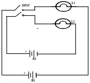
DPST Switch Circuit
Any electrical load or power supply has at least two terminals.
Since this switch provides two inputs and two outputs, you can use it to control one load from a single power supply, or two separate loads from two different power supplies.
In the circuit above, two distinct loads are connected to two separate power supplies.
We can see that Load 1 (Lamp 1) is connected to Battery 1 (Source 1), and Load 2 (Lamp 2) is connected to Battery 2 (Source 2).
When the switch is turned ON, both lamps light up at the same time.
When the switch is turned OFF, both lamps turn off together.
In this way, the DPST switch controls both loads in the circuit simultaneously.
Advantages
The main advantages of a DPST switch include:
- It can open or close two independent circuits at the same time.
- It operates with two separate circuit paths.
- Both input‑output pairs function simultaneously.
- A DPST switch is equivalent to two SPST switches combined in one unit.
Disadvantages
Some limitations of DPST switches are:
- It only provides simple ON/OFF switching.
- It is a more complex ON/OFF switch that connects or disconnects two circuits at once.
- When switched ON, current flows to both loads; when switched OFF, both loads turn off.
Applications
DPST switches are widely used in these applications:
- They are ideal for mains supply switching, as they can disconnect both live and neutral lines.
- Used in breaker control logic circuits and as industrial selector switches.
- Allow two circuits to be controlled together (both ON or both OFF).
- Used to safely isolate power from a load.
- Enable two separate power sources to be switched simultaneously.
- Commonly used in 240V applications.
- Often used to control equipment that uses both live and neutral supply lines.
- Frequently used to control electric heating loads with temperature-sensing elements, automatically opening or closing contacts based on external temperature changes. In this role, the switch acts as a thermostat.
Conclusion
This completes the overview of the DPST switch.
Externally, it looks similar to a standard SPST switch, but internally it interrupts two current-carrying conductors instead of just one. This makes it ideal for controlling and isolating loads that use two ungrounded conductors and operate on 240V single‑phase power.
Here’s a question for you:
What is a DPDT switch?
Related Articles
Diode Dynamics: Real-World Behavior in Fast Power and RF Circuits

Christopher Anderson
Christopher Anderson has a Ph.D. in electrical engineering, focusing on power electronics. He’s been a Senior member of the IEEE Power Electronics Society since 2021. Right now, he works with the KPR Institute of Engineering and Technology in the U.S. He also writes detailed, top-notch articles about power electronics for business-to-business electronics platforms.
Subscribe to JMBom Electronics !


