


Float Switch: Working Principle & Applications
Catalog
What is a float switch?Construction of a Float SwitchFloat Switch Working PrincipleElectromagnetic Float Switch OperationMechanical Float Switch OperationSpecificationsTypes of Float SwitchAdvantages of Float SwitchesDisadvantages of Float SwitchesApplicationsSummaryRelated ArticlesA float switch is a device widely used across industrial processes for point-level liquid detection. It signals whether a liquid level is in a normally open or normally closed state at a defined set point.
These switches are capable of detecting conditions including foam, dielectric properties, conductivity, pressure, temperature, vacuum, vapors, condensation, boiling, vibration, and bubble formation. As a result, they are suitable for use with nearly all types of liquids.
Float switches operate on a non-contact switching principle and require no external power supply. Thanks to their straightforward operating mechanism, they are used in an extremely broad range of applications—from general industrial uses to process manufacturing facilities and the shipbuilding industry.
This article provides a complete overview of the float switch, including its working principle and typical applications.
What is a float switch?
A float switch is a contact-type liquid level sensor that uses a float to actuate a switch mechanism inside a tank. It is also commonly referred to as a level sensor.
Float switches play a critical role in controlling equipment such as pumps and alarms when the liquid level rises or falls to a predefined set point.
The symbol for a float switch is shown below. These switches are available in a wide range of sizes, from compact miniature models to large industrial units.
There are two main types of float switches: magnetic (electromagnetic) and mechanical float switches.
Would you like me to keep polishing your float switch technical document into full professional English?
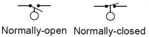
Switch Symbols
Construction of a Float Switch
An electromagnetic float switch is typically constructed from three main components: a stem, a reed switch, and a permanent magnet.
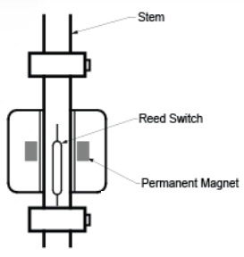
construction of this electromagnetic switch
Stem
The stem is the rigid body of the switch, which directly mounts the switch assembly to the vessel or end unit.
Depending on application requirements, the stem can be made from either plastic or metal.
Reed Switch
The reed switch is hermetically sealed inside the stem of the float switch.
Stems are most commonly manufactured from stainless steel or plastic.
The float incorporates a sealed magnet that moves up and down along the stem as the fluid level rises and falls.
Permanent Magnet
The permanent magnet inside the float moves in tandem with the fluid level along the guide tube.
A reed contact is installed inside the guide tube; as the float’s magnet approaches, it actuates the reed contact through the non‑magnetic walls of the tube.
Float Switch Working Principle
The operation of a float switch is based on the principle of buoyancy.
When there is no liquid or an insufficient liquid level, the float remains positioned at the top surface and activates an alarm signal.
When a sufficient liquid level is reached, the float submerges accordingly and deactivates the alarm.
Both types of float switches operate on this same fundamental principle, although their actual functioning varies based on their mechanical and electrical construction.
Below is how each type works.
Electromagnetic Float Switch Operation
As described in the construction section, the magnet integrated within the float moves up and down along the stem as the liquid level rises and falls.
The reed switch is securely installed inside the stem or mounted within the tank containing the liquid being monitored.
When the magnet approaches the reed switch, it actuates the switch and completes (or opens) the electrical circuit.
This triggers an alarm, controls external equipment such as pumps, or performs other control functions – for example, switching the power supply on or off.
Mechanical Float Switch Operation
The mechanical float switch is the most common type of liquid level switch, used to detect the presence of liquid inside a tank or vessel.
This device features a float that rises and falls with the liquid level.
This style of float switch includes an arm or lever that moves in response to changes in liquid level. A rod runs through the center of the arm; one end is fixed at the top, while the other connects to a lever that acts as the actuator.
When the liquid level in the vessel is high, the upward buoyancy acting on the float causes the lever to move, which in turn switches on the power supply to connected equipment such as pumps or alarms.
When the liquid level in the tank is low, the float drops, and the lever returns to its original position. This stops the power supply or deactivates the connected device. The switch maintains its state based on buoyancy and gravity, without relying on magnetic components.
Specifications
The float switch features the following specifications:
- Rated voltage: 220–240V
- Maximum current: 10A
- Ingress protection rating: IP68
- This switch is ideally suited for water level control in both overhead and underground water tanks. It enables automatic pump start and stop functions.
- Designed with a fully mechanical operating principle, it requires no electronic sensors. It can also be connected to an alarm system to provide basement flood detection alerts.
Types of Float Switch
Float switches are available in two configurations: horizontal and vertical.
Horizontal Float Switch
Horizontal float switches are mounted onto the sidewalls of water tanks, making them ideal for installations where the top and bottom of the tank are inaccessible.
As the liquid level rises and falls, the movement of the float activates the reed switch at a preset level.
The float is attached to a hinge mechanism. When the float moves into position, it brings a magnet close to the reed switch, causing the circuit to open or close.
Horizontal Float Switch
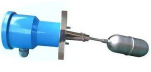
Vertical Float Switch
A vertical float switch consists of a stem with two magnetic floats. One float is fixed at the top of the tank, while the other moves freely with the liquid level.
The moving float slides along the stem as the liquid level rises and falls. The stem contains one or more hermetically sealed reed switches. When the float nears a reed switch, the magnetic force opens or closes the electrical circuit.
In this way, the movement of the float in response to changing liquid levels triggers the switch to operate at a predetermined level.
Vertical Float Switch
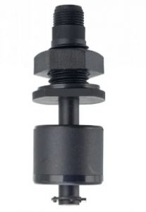
Float Switch with Arduino
Below is how to interface a float switch with an Arduino. In this project, the switch is used to detect the water level and depth inside a tank. This float switch is an electromagnetic device that closes (activates) when it comes into contact with water.
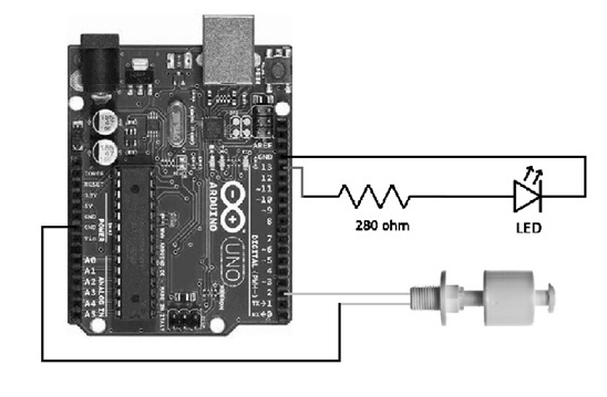
Interfacing an Arduino with the Float Switch
This switch is constructed from plastic.
- Power rating: approximately 10W
- Operating temperature: 10°C to 85°C
- Maximum switching current: 0.5A
- Voltage rating: 100V DC
Wiring the switch to an Arduino is straightforward. The float switch typically has two terminals: VCC and GND. Connect the switch’s GND terminal to the GND pin on the Arduino, and the other terminal to one of the Arduino’s digital input pins.You can easily visualize the switch operation by adding an LED to the Arduino circuit. The LED will light up when the float switch is triggered by a high water level.
Arduino Code for Float Switch Water Level Monitoring
Below is the Arduino code to interface a float switch and monitor water levels in a tank:
// Define pins for the float switch and status LED
int floatSwitchPin = 2;
int statusLED = 3;

// Variable to store the float switch state (initialized to HIGH for INPUT_PULLUP)
int switchState = 1;

void setup() {
  // Initialize serial communication at 9600 baud (for status monitoring)
  Serial.begin(9600);

  // Set float switch pin as input with Arduino's internal 10K pull-up resistor
  pinMode(floatSwitchPin, INPUT_PULLUP);

  // Set LED pin as output to indicate water level status
  pinMode(statusLED, OUTPUT);
}

void loop() {
  // Read the current state of the float switch
  switchState = digitalRead(floatSwitchPin);

  // Check if water level is high (float switch activated)
  if (switchState == HIGH) {
    digitalWrite(statusLED, HIGH); // Turn on LED
    Serial.println("WATER LEVEL – HIGH"); // Print status to Serial Monitor
  }
  // Water level is low (float switch deactivated)
  else {
    digitalWrite(statusLED, LOW); // Turn off LED
    Serial.println("WATER LEVEL – LOW"); // Print status to Serial Monitor
  }

  // 1-second delay to stabilize sensor readings
  delay(1000);
}
Uploading and Testing the Code
Once the code is ready, upload it to your Arduino board by selecting the correct port in the Arduino IDE. After a successful upload, you can test the float switch operation to verify it works as intended.
Program Walk through
- Variable Initialization: First, we define pins for the float switch (pin 2), status LED (pin 3), and initialize
switchStateto1(matching the default HIGH state of the INPUT_PULLUP configuration). - Setup Function:
- Main Loop (Continuous Execution):
Expected Behavior
After successful code upload:
- When the water level in the tank rises and activates the float switch, the connected LED turns ON, and "WATER LEVEL – HIGH" appears in the Serial Monitor.
- When the water level drops (float switch deactivated), the LED turns OFF, and "WATER LEVEL – LOW" is displayed.
- This cycle repeats continuously with a 1-second interval between sensor checks.
Advantages of Float Switches
- Simple, low-cost installation and mounting.
- No auxiliary power supply required for operation.
- Compatible with a wide range of liquids (including acids, chemicals, and other corrosive fluids).
- Potential-free operation with switching voltage up to 230V AC.
- Immune to surface disturbances like bubbling, foaming, or ripples in the liquid.
- Can be paired with temperature sensors/switches for combined monitoring.
- Unaffected by fluid conductivity or dielectric constant.
Disadvantages of Float Switches
- Moving parts are prone to corrosion, clogging, or physical damage over time.
- Fouling (buildup of debris) can cause unreliable movement or complete seizure of the float mechanism.
- Float activation relies entirely on direct contact with the liquid.
- Turbulence in the liquid may cause false triggers or erratic float movement.
- Sticky or viscous fluids can prevent the float from moving freely.
- Regular maintenance is required to ensure the float is not obstructed.
Applications
Typical applications of float switches include:
- Automatically turning pumps ON and OFF, or opening and closing solenoid valves.
- Activating tank level alarms to prevent overflow and alert users to potential hazards.
- Protecting heaters and other electrical equipment from damage or unsafe operating conditions.
- Monitoring liquid levels in a wide range of industrial and residential systems, often connected to valves, pumps, or alarms for user feedback.
- Controlling water levels in industrial washing machines.
- Managing condensate levels in air conditioning and refrigeration systems.
- Handling filling and emptying operations in beverage processing tanks.
- Regulating water levels in potable water tanks, rainwater harvesting systems, wastewater systems, and sewage applications, with pumps automatically activated by the rising or falling float.
- Detecting high water levels in sump pumps and sewage pits to trigger pump operation and prevent flooding.
Summary
This overview covers the fundamentals of float switches, their operating principle, and common uses. The primary function of a float switch is to detect liquid levels inside a tank or container.
Here is a quick review question:
What is another common name for a float switch?
Related Articles
Diode Dynamics: Real-World Behavior in Fast Power and RF Circuits

Christopher Anderson
Christopher Anderson has a Ph.D. in electrical engineering, focusing on power electronics. He’s been a Senior member of the IEEE Power Electronics Society since 2021. Right now, he works with the KPR Institute of Engineering and Technology in the U.S. He also writes detailed, top-notch articles about power electronics for business-to-business electronics platforms.
Subscribe to JMBom Electronics !


