


Guide to Latching Switches
Catalog
What is a Latching Switch?How Does a Latching Switch Work?Latching Switch CircuitWorkingTypes of Latching SwitchMomentary Switch vs. Latching SwitchAdvantages of Latching SwitchesDisadvantages of Latching SwitchesApplicationsRelated ArticlesSwitches are typically divided into two main types based on their operating behavior and latching characteristics: latching and non-latching. There are many switch variants across different categories—including electronic switches, normally open (NO), normally closed (NC), and momentary switches, among others.
The key difference in operation is straightforward:
A latching switch stays in its activated (on) state once triggered, and remains on until the input signal or pressure is deliberately removed or deactivated. By contrast, a non-latching (momentary) switch only stays on while pressed, and automatically turns off when released.
Today, these switches are widely used in countless electronic devices and systems. This article provides an overview of the latching switch, including how it works and its typical applications.
What is a Latching Switch?
A latching switch is a type of switch that maintains its state (either on or off) without needing constant pressure or power to hold it in position. These switches are commonly used in household applications such as light switches, stereo systems, and central heating controls. The symbol for a latching switch is shown below.
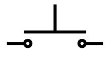
Latching Switch Symbol
Unlike other switches, a latching switch will remain in the ON position and continue to operate even after the pressure on the switch is released. These switches are commonly used in alarm systems: once triggered, the alarm will stay on indefinitely until the entire system is manually deactivated.
Typically constructed from metal or plastic, latching switches are available in a wide variety of models, all of which operate using a latching mechanism to maintain their set state.
How Does a Latching Switch Work?
A latching switch operates by toggling its state with each press. When you apply pressure to the switch, it turns ON and stays that way—even after you release the pressure. It will only turn OFF when you press the switch a second time. In short, the operator activates it once, and it remains on until manually deactivated by a second press.
Latching Switch Circuit
Below is a typical latching switch circuit built with transistors. This circuit can be constructed using common electronic components, including a 5V to 12V power supply, a PNP 2N4403 transistor, an NPN 2N4401 transistor, a relay, a 1N4007 diode, and resistors (1KΩ, 10KΩ, and 4.7KΩ).
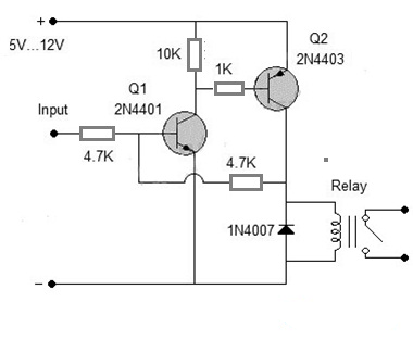
Latching Switch Circuit
A latching circuit “locks” its output state as soon as an input signal is applied, and maintains that state even after the input signal is removed. It will stay in this position indefinitely until power is reset or an external signal is applied to turn it off.
This circuit behaves very similarly to an SCR (Silicon Controlled Rectifier) and is often used as an alternative when an SCR is not available. It is particularly useful in alarm circuits: once triggered, the buzzer will sound continuously until power is manually disconnected.
In this design, the latching function is achieved using transistors such as the 2N4401 (NPN) and 2N4403 (PNP). A relay is used at the output to control the target electronic device or application.
Working
This simple latching circuit operates on a 5V to 12V power supply. It uses two transistors: an NPN 2N4401 (designated Q1) and a PNP 2N4403 (designated Q2). When an input signal is applied to the base of Q1, the transistor turns on, connecting the base of Q2 to ground. This activates Q2, which in turn energizes the relay connected to its collector.
A 4.7KΩ resistor provides feedback from Q2's collector back to Q1's base. This creates a self-sustaining loop, keeping Q1 conducting indefinitely—even after the original input signal is removed—until the power supply is disconnected. The 1N4007 diode protects the circuit by suppressing reverse current and voltage spikes.
This circuit is widely used in fire alarms, burglar alarms, and car anti-theft security systems, often serving as a practical alternative to an SCR.
Types of Latching Switch
Latching switches come in four main configurations: SPDT, DPDT, DPST, and SPST. Below is an overview of each type and its specifications.
SPST Latching Switch
SPST (Single-Pole, Single-Throw) latching switches typically have a rating of 2A at 250VAC and an operational life of up to 50,000 cycles. They are commonly found in ticket dispensers, electronic kiosks, and various industrial applications.
Key features include:
- Metal construction
- Waterproof options available
- Operates in harsh environments, from -40°C to +70°C
- Dust, water, and dirt-resistant
- Corrosion-proof and non-magnetic, suitable for both indoor and outdoor use
SPST Latching Switch
SPDT Latching Switch
This is another common type of latching switch, with key specifications as follows:
- Switch operation: Latching
- Mounting type: Panel mount
- Contact configuration: SPDT (Single Pole, Double Throw)
- Panel cutout size: 19.1 mm
- IP rating: IP67
- Voltage rating: 250 / 125 V AC
- Contact current rating: 16 A, 26 A
- Actuator shape: Flat
- Actuator type: Push‑button
- Terminal type: Quick‑connect
SPDT
DPDT Latching Switch
These switches are designed with a high operating force, making them ideal for various foot-control applications. Key specifications include:
- Switch operation: Latching
- Mounting type: PCB mount
- Contact configuration: DPDT (Double Pole, Double Throw)
- Panel cutout size: 12.2 mm (diameter)
- Contact current rating: 2 A, 4 A
- Actuator shape: Cylindrical
- Contact DC voltage rating: 12 V, 24 V
- Terminal type: Solder lug
- Actuator type: Plunger cap
- Voltage rating: 250 V / 125 V AC
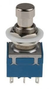
DPDT
DPST Latching Switch
These non‑illuminated switches are suitable for use in Class II appliances. They feature silver contacts and are available in various switching configurations. A transparent cover protects the switch from water ingress, dust, and other contaminants.
Key specifications include:
- Switch operation: Latching
- Mounting type: Panel mount
- Contact configuration: DPST (Double Pole, Single Throw)
- Panel cutout size: 30 × 22 mm
- IP rating: IP40
- Actuator color: Green
- Voltage rating: 230 V AC
- Contact current rating: 16 A at 250 V AC
- Actuator shape: Rectangular
- Terminal type: Tab terminal
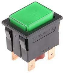
DPST
Momentary Switch vs. Latching Switch
The key differences between momentary and latching switches are summarized below.
| Momentary Switch | Latching Switch |
|---|---|
| Also known as a push-to-make or non-latching switch. | Also known as a maintained or push-on/push-off switch. |
| Requires continuous pressure from the operator to stay activated. | Does not require continuous pressure; it locks into position. |
| Mechanically simpler in design. | Generally more complex mechanically. |
| Typically more compact in size. | Often physically larger. |
| Lower cost. | Higher cost. |
Advantages of Latching Switches
- Available in compact sizes.
- High load-handling capacity.
- Highly reliable, secure, and long service life.
- Replaces traditional crossbar switches in many applications.
- Provides greater user comfort and ease of control.
- Operates silently and maintains state continuously.
- Very fast connection to devices.
Disadvantages of Latching Switches
- Primarily suited for low-risk applications where manually holding a switch would be inconvenient. They would be unsuitable for situations requiring constant manual pressure, such as holding a switch to keep a light on.
- Operation is typically limited to manual actuation.
Applications
Latching switches are used in a wide variety of everyday and industrial applications:
- The most common use is in household light switches.
- They are also found in consumer electronics such as computers, televisions, and other household electrical devices.
- Their versatile operating modes make them suitable for many different applications.
- In the home, they are used for light switches, stereo systems, and central heating controls.
- In industry, they are used in equipment like spa controllers and tattoo machines.
- Many devices rely on latching functionality, giving them broad use in various electronic circuits.
- They are also employed in SCR (Silicon Controlled Rectifier) circuits and similar control systems.
This covers the basics of latching switches—how they work and where they’re used. A latching switch stays in its set position once pressed and does not return to its original state until pressed again. These switches are also known as maintained switches.
Here’s a question for you: What is a relay switch?
Related Articles
Diode Dynamics: Real-World Behavior in Fast Power and RF Circuits

Christopher Anderson
Christopher Anderson has a Ph.D. in electrical engineering, focusing on power electronics. He’s been a Senior member of the IEEE Power Electronics Society since 2021. Right now, he works with the KPR Institute of Engineering and Technology in the U.S. He also writes detailed, top-notch articles about power electronics for business-to-business electronics platforms.
Subscribe to JMBom Electronics !


