


Guide to Displacement Transducer
Catalog
What is a Displacement Transducer?Displacement Transducer Circuit DiagramDisplacement Transducer CalibrationDisplacement Transducer TypesAdvantages and Disadvantages of Displacement TransducersApplications of Displacement TransducersRelated ArticlesA position sensor is a device used to track and measure any changes in the position of an object within a machine or nearby area. It converts these changes into signals that can be transmitted, processed, or used for control purposes. There are various types of position sensors, with the displacement transducer being a specific type. Unlike standard sensors that detect the presence of an object, displacement sensors detect when an object moves from one place to another. By measuring the amount of displacement, they help determine an object’s size, thickness, and height. This article provides an overview of the displacement transducer, its function, and its applications.
What is a Displacement Transducer?
A displacement transducer is an electromechanical device that converts the movement of an object into electrostatic, electromagnetic, or magnetoelectric signals. These signals are then read and interpreted as data. Displacement transducers come in various types, including linear and rotary versions. They are also useful for measuring the physical distance between the sensor and a target. Most displacement transducers can measure both static and dynamic displacements, making them ideal for monitoring vibrations of an object. The range of displacements they can measure typically spans from micro inches to several feet.
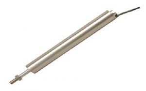
Displacement Transducer
The working principle of a displacement transducer is based on the highly reliable inductive measurement method. These transducers are robust, user-friendly, and capable of achieving high precision. They provide dependable measurement results across various fields, including production, research, and development.
Displacement Transducer Circuit Diagram
The circuit shown below utilizes an inductive displacement transducer. This setup is designed to measure displacement using the principles of inductive transduction. The inductive transducer in the circuit converts the displacement of the object into an electrical signal, which can then be processed or used for further analysis.
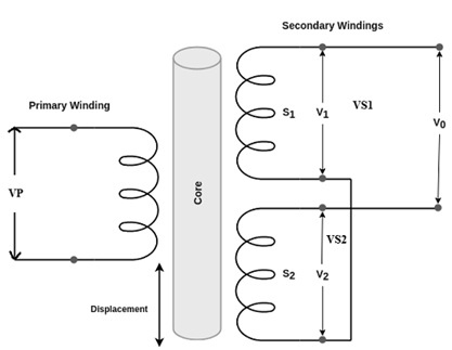
Displacement Transducer Circuit
In the circuit above, the transformer consists of a primary winding and two secondary windings. These two secondary windings are connected in series opposition, meaning their endpoints are linked together.
When a voltage VPV_PVP is applied to the primary winding, it induces voltages across each of the secondary windings, denoted as VS1V_{S1}VS1 and VS2V_{S2}VS2. The output voltage V0V_0V0 is taken from the first points of the secondary windings, and it can be expressed as:V0=VS1−VS2V_0 = V_{S1} - V_{S2}V0=VS1−VS2
The transformer used in this circuit is a differential transformer because it generates an output voltage based on the difference between VS1V_{S1}VS1 and VS2V_{S2}VS2.
- When the core is positioned at the central point, the induced voltages across both secondary windings S1S1S1 and S2S2S2 are equal, which results in an output voltage V0=0V_0 = 0V0=0. This indicates no displacement.
- If the core is displaced above the central position, the emf induced in coil S1S1S1 becomes greater, so V1>V2V_1 > V_2V1>V2.
- Similarly, if the core is displaced below the central position, the emf induced in coil S2S2S2 is greater, meaning V2>V1V_2 > V_1V2>V1.
This change in the induced voltages allows the displacement to be measured accurately.
In the two cases, when the core is displaced upward or downward, the magnitude of the output voltage V0V_0V0 is proportional to the core's position relative to the center.
To measure the displacement of an object, the object must be attached to the central core. As the object moves in a straight line, the position of the core changes, and consequently, the output voltage V0V_0V0 will also vary. By measuring the output voltage, we can determine the displacement. The phase and magnitude of the output voltage indicate the displacement and the direction of the object's movement, respectively.
Displacement Transducer Calibration
Calibration of displacement transducers is crucial for ensuring the accuracy, repeatability, and reliability of the measurement results. These transducers are commonly used in both academic and industrial applications, so regular calibration is essential.
Although calibration can be time-consuming, it becomes easier with the use of calibration equipment. With such tools, calibration can be done quickly by simply adjusting a knob and pressing a button, making the process more efficient while maintaining precise measurements.
The calibration system for the displacement transducer is a comprehensive solution designed to calibrate these sensors for displacements up to 50.8mm with a resolution of 13 microns. It can be used with any system, though it comes with custom software for fast and easy calibration when paired with National Instruments (NI) systems.
Displacement Transducer Types
There are various types of displacement transducers, also known as displacement sensors, including potentiometers, strain gauges, capacitive sensors, and LVDTs. Here's a brief overview of some common types:
Resistive Transducer
A resistive transducer, also known as a variable resistance transducer, operates on the principle of variable resistance transduction. This type is one of the most commonly used displacement transducers, and it is frequently employed to measure a variety of physical quantities such as pressure, displacement, force, temperature, and vibrations. It converts these quantities into an electrical signal for further processing or analysis.
Resistive Transducer
Capacitive Transducer
A capacitive transducer is a passive type of transducer that operates by using external power. It is commonly used to measure parameters such as pressure, displacement, movement, force, velocity, and more. The functioning of this transducer is based on the principle of variable capacitance.
In this type of transducer, the capacitance changes due to several factors, such as the dielectric constant, the overlapping of plates, and the variation in the distance between the plates. This is a passive device, meaning that equal and opposite charges are generated on the capacitor plates when a voltage is applied across them. The plates are separated by a dielectric material, and any change in the position or properties of the plates results in a change in capacitance, which can be measured to determine the displacement or other parameters.
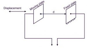
Capacitive Transducer
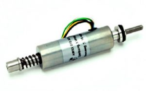
Linear Variable Differential Transformer (LVDT)
The Linear Variable Differential Transformer (LVDT) is a type of displacement transducer that consists of three symmetrically spaced coils. The central coil is the primary coil, while the remaining two coils are the secondary coils. These secondary coils are connected in series and are positioned symmetrically with respect to the primary coil.
The LVDT is widely used to measure linear displacement due to its high accuracy, reliability, and sensitivity. The operation of the LVDT relies on the change in the voltage induced in the secondary coils when the core inside the transformer moves. This displacement causes a variation in the output voltage, which is then used to calculate the position of the core.
LVDT
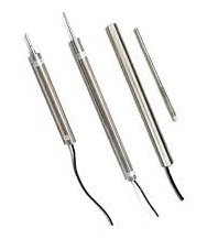
Inductive Transducer
An inductive transducer is a type of displacement transducer that operates on the principle of electromagnetic induction or transduction. It is used to measure various physical quantities such as force, displacement, velocity, pressure, acceleration, and torque. The working principle of an inductive transducer involves the variation of mutual or self-inductance in response to changes in the measured physical quantity.
A common example of an inductive transducer is the Linear Variable Differential Transformer (LVDT), which uses this principle to measure displacement with high precision. The inductance of the coils in an inductive transducer changes when there is a movement in the position of the core, and this change is used to calculate the displacement.
Inductive Transducer
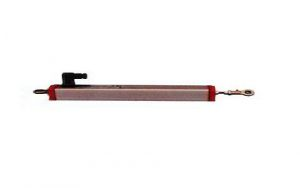
Strain Gauge
A strain gauge displacement transducer is used to convert physical quantities like pressure, displacement, or load into mechanical strain, which is then converted into an electrical output using mounted strain gauges on an elastic body. These transducers are commonly used to measure displacements in the range of 0 to 10 mm.
One of the key advantages of a strain gauge displacement transducer is its short body length compared to LVDTs, making it more compact. Additionally, it is free from electromagnetic interference, making it suitable for use in environments with varying electromagnetic fields. Strain gauge transducers are known for their high stability and reliable performance, which is why they are widely used in many precision measurement applications.
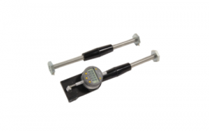
Mechanical Strain Gauge
Advantages and Disadvantages of Displacement Transducers
Advantages:
- Excellent Linearity: Displacement transducers offer highly linear responses, which improves measurement accuracy.
- High Accuracy: These transducers are known for their extremely high accuracy in measuring displacement.
- Outstanding Resolution: Some displacement transducers have a resolution as fine as 0.01 µm.
- Magnetic Field Tolerance: They are tolerant to high magnetic fields, making them suitable for environments with strong electromagnetic interference.
- Resistance to Harsh Environments: Displacement transducers can function in radioactive environments and extreme temperature ranges.
- Strong Design and Stability: They have a durable design and maintain excellent stability over time.
- Flexible Mounting: These transducers can be mounted in any orientation (horizontal, vertical, etc.).
- Low Power Consumption: LVDTs (Linear Variable Differential Transformers) specifically have very low power consumption.
- Sensitive and Easy to Maintain: They are highly sensitive and simple to align and maintain.
- Low Hysteresis Loss: These transducers exhibit low hysteresis, meaning their response is consistent even after repeated use.
- Wide Measurement Range: The measurement range for displacement transducers is typically much higher compared to other types.
- Frictionless Operation: Many displacement transducers, like LVDTs, are frictionless devices, which enhances their reliability and lifespan.
Disadvantages:
- Need for High Displacement: Displacement transducers require significant displacement to generate a high output voltage.
- Susceptibility to Magnetic Fields: They need shielding because they are sensitive to magnetic fields, which could affect their performance.
- Affected by Vibrations and Temperature: Their performance can be influenced by vibrations and temperature fluctuations in the environment.
- External Demodulator Requirement: To get a DC output, displacement transducers often require an external demodulator.
- Limited Dynamic Response: The dynamic response of displacement transducers may be limited, meaning they may not react as quickly to very fast changes.
Applications of Displacement Transducers
- Measuring Relative Movement: They are used to measure the relative movement between the sensor tip and the rotating shaft in machinery.
- Measuring Small Vibrations: In rigid machinery, they can detect extremely small vibrations transmitted from the shaft to the machine casing.
- Industrial & Public Sector: Commonly used in automation, aerospace, aircraft, power turbines, and hydraulics.
- Measurement Range: LVDTs are particularly useful for measuring displacements ranging from millimeters to centimeters.
- CNC Machines: Used in CNC machines to accurately measure displacement.
- Measuring Metal Sheet Thickness: Employed in industries to measure the thickness of rolled metal sheets.
- Tension Measurement: Used in channels for precise tension measurement.
- Flight Control Systems: RVDT (Rotary Variable Differential Transformer) displacement transducers are used in aircraft flight control systems.
- Force, Acceleration & Pressure Measurement: Potentiometer types of displacement transducers are often used for measuring force, acceleration, and pressure.
Overview of Displacement Transducers
Displacement transducers convert mechanical vibrations or motion, particularly linear motion, into electrical signals (current or voltage). Examples of their applications include measuring displacement, bending strain, and cracks within materials such as concrete or metal. The primary function of a displacement transducer is to provide an electrical output that corresponds to the displacement of an object.
What is the Function of a Transducer?
The function of a transducer is to convert one form of energy (such as mechanical, thermal, or electrical) into another form, typically for measurement, control, or analysis purposes. In the case of a displacement transducer, it converts mechanical motion (displacement) into an electrical signal (voltage or current) that can be easily measured, processed, and analyzed.
Related Articles
Diode Dynamics: Real-World Behavior in Fast Power and RF Circuits

Christopher Anderson
Christopher Anderson has a Ph.D. in electrical engineering, focusing on power electronics. He’s been a Senior member of the IEEE Power Electronics Society since 2021. Right now, he works with the KPR Institute of Engineering and Technology in the U.S. He also writes detailed, top-notch articles about power electronics for business-to-business electronics platforms.
Subscribe to JMBom Electronics !


